
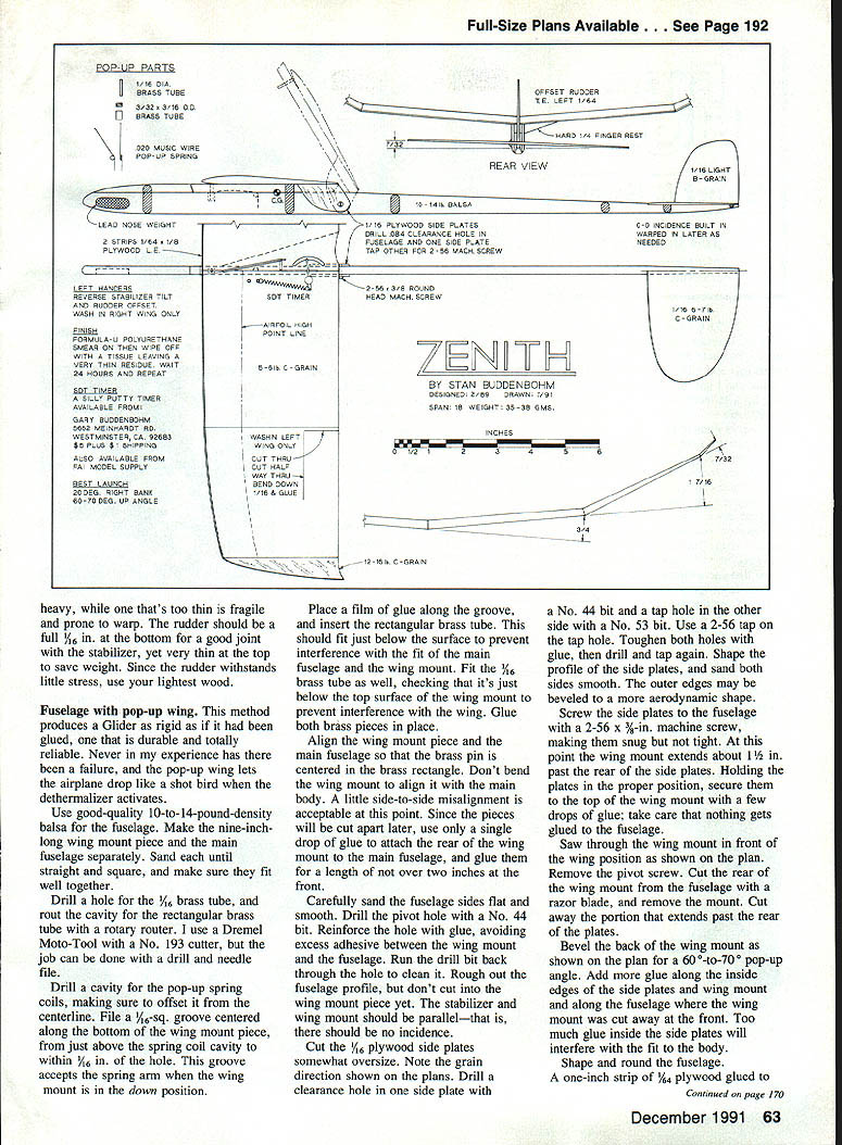
Zenith
Stan Buddenbohm
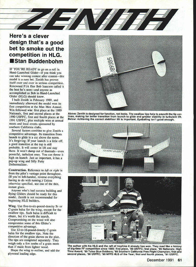
Here's a clever design that's a good bet to smoke out the competition in Hand-Launched Glider (HLG).
If you're ready to go on a roll in HLG—if you think you can take winning contest after contest—this model is a sure bet. Zenith has proven itself repeatedly in serious competition. Renowned F1A flier Bob Isaacson called it the best he's seen—and anyone as accomplished as Bob in Hand-Launched Glider should know.
I built Zenith in February 1989, and immediately afterward the model won its first competition at the Max Men Annual. Win followed win: first place at the 1989 Nationals; first and second places at the 1990 USFFC; first and fourth places at the 1991 USFFC; plus multiple wins at annual meets and local events sponsored by southern California clubs.
Several factors combine to give Zenith a competitive advantage. Its transition from launch to glide is a cut above the norm. It's forgiving: if your launch is a little off, a good transition at the top is still probable. It will center in lift and stay there. It won't dump out of thermals—even powerful, turbulent ones. You can throw it high on launch. Just as important, it has a pop-up wing and a Silly Putty Dethermalizer.
Construction
Reference to left or right is from the pilot's vantage point throughout. (If you're left-handed, reverse everything having to do with turning.) Unless otherwise specified, use thin, instant glues.
Anyone who's had success building and flying gliders should be ready for this model. Zenith is not recommended for beginning HLG builders.
Wing
- Wood: Use 5–6 lb density B- or C-grain balsa for the main wing panels, except for the swallow tips. Use 12–16 lb density C-grain balsa for the swallow tips. Note the grain direction shown on the plan. The tips are completed separately. They weigh only a few tenths of a gram more than if made from lighter wood.
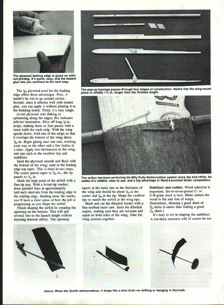
- Shape the wing outline, and add the plywood leading edge.
Advantages of plywood for the leading edge:
- You needn't wet it to go around curves.
- Since it adheres well with instant glue, you can apply it without pinning the wing to the building board.
- It's very tough.
Avoid plywood that flakes or splinters along the edges—this indicates inferior lamination.
- Slice off long, thin strips (about 1/16–1/8 in wide), making three or four passes with a razor knife for each strip. Strip the wing upside down; hold the strips so each overlaps the bottom of the wing by about 1/8 in. Begin gluing near one end and work your way to the other a few inches at a time. Apply two thicknesses of plywood over the wing, and lighter coverage on the swallow tips and stabilizer as the plan specifies.
- Sand the plywood smooth and flush with the bottom of the wing. Sand the leading-edge top taper in two steps: center panels taper to about 3/32 in, tip panels to about 1/16 in.
- Mark the high point of the airfoil with a fine-tip pen. With a broad-tip marker, draw parallel lines approximately 1/2 in apart from leading edge to trailing edge. Sanding away the marks will give you a clear sense of progress as you shape the airfoil.
- Finish shaping the airfoil. Creating an upsweep on the bottom will add several feet of launch height but may harm thermal ability; weigh the tradeoff for your flying style. The upsweep should taper at the same rate as the thickness: about 1/16 in at the center and 1/32 in at the tip.
- Shape the swallow tips to match the airfoil and wing tips.
- Mark and cut the dihedral breaks with a fine-toothed razor saw. Sand the dihedral angles, making sure they are accurate and equal on both sides. Glue the wing sections together.
Stabilizer and rudder
- Wood: Six- to seven-pound C- or C-B-grain stock is best. Make certain the wood is flat and free of warps. Sometimes thinning a good 3/32 in sheet down to 1/16 in is easier than finding a good 1/16 in sheet.
- It's easy to err when shaping the stabilizer: a too-thick structure will be too heavy, while one that's too thin is fragile and prone to warp.
- The rudder should be a full 1/16 in at the bottom for a solid joint with the stabilizer, yet very thin at the top to save weight. Since the rudder sustains little stress, use your lightest wood.
- Apply plywood leading-edge strips to the stabilizer as you did for the wing (thin strips, well glued and sanded flush).
- Glue the rudder to the stabilizer and the stabilizer to the fuselage at the offset and angle shown on the plan. Be careful to get this accurate. Put the model in a jig and measure the stabilizer tilt before gluing.
Fuselage with pop-up wing
This method produces a glider as rigid as if it had been glued, durable and reliable. The pop-up wing lets the airplane drop like a shot bird when the dethermalizer activates.
- Wood: Use good-quality 10–14 lb density balsa for the fuselage.
- Make the nine-inch-long wing mount piece and the main fuselage separately. Sand each until straight and square, and make sure they fit well together.
- Drill a hole for the 1/16-in brass tube and rout the cavity for the rectangular brass tube with a rotary router (a Dremel Moto-Tool with a No. 193 cutter works well); the job can also be done with a drill and needle file.
- Drill a cavity for the pop-up spring coils, making sure to offset it from the centerline. File a 1/16-in groove centered along the bottom of the wing mount piece, from just above the spring coil cavity to within 1/8 in of the hole. This groove accepts the spring arm when the wing mount is in the down position.
- Place a film of glue along the groove, and insert the rectangular brass tube so it fits just below the surface to prevent interference with the main fuselage and wing mount. Fit the 1/16-in brass tube as well, checking that it is just below the top surface of the wing mount. Glue both brass pieces in place.
- Align the wing mount piece and the main fuselage so the brass pin is centered in the brass rectangle. Don't bend the wing mount to align it with the main body. A little side-to-side misalignment is acceptable at this point. Since the pieces will be cut apart later, use only a single drop of glue to attach the rear of the wing mount to the main fuselage, and glue them for a length of not over two inches at the front.
- Carefully sand the fuselage sides flat and smooth. Drill the pivot hole with a No. 44 bit; reinforce the hole with glue, avoiding excess adhesive between the wing mount and fuselage. Run the drill bit back through the hole to clean it.
- Rough out the fuselage profile, but don't cut into the wing mount piece yet. The stabilizer and wing mount should be parallel—there should be no incidence at this stage.
- Cut the 1/16-in plywood side plates somewhat oversize. Note the grain direction shown on the plans. Drill a clearance hole in one side plate with a No. 44 bit and a tap hole in the other side with a No. 53 bit. Use a 2-56 tap on the tap hole. Toughen both holes with glue, then drill and tap again. Shape the profile of the side plates, and sand both sides smooth. The outer edges may be beveled to a more aerodynamic shape.
- Screw the side plates to the fuselage with a 2-56 x 3/8-in machine screw, making them snug but not tight. At this point the wing mount extends about 1-1/2 in past the rear of the side plates. Holding the plates in the proper position, secure them to the top of the wing mount with a few drops of glue; take care that nothing gets glued to the fuselage.
- Saw through the wing mount in front of the wing position as shown on the plan. Remove the pivot screw. Cut the rear of the wing mount from the fuselage with a razor blade and remove the mount. Cut away the portion that extends past the rear of the plates.
- Bevel the back of the wing mount as shown on the plan for a 60°–70° pop-up angle. Add more glue along the inside edges of the side plates and wing mount and along the fuselage where the wing mount was cut away at the front. Avoid excess glue inside the side plates—it will interfere with the fit to the body.
- Shape and round the fuselage. A one-inch strip of 1/64-in plywood glued to the top of the fuselage just behind the wing mount will protect the fuselage from pop-up damage.
Assembly and finish
- Install the wing mount, securing the front with a rubber band.
- Sand the bottom of the wing center dihedral joint flat for a square fit with the wing mount. Hold the wing in proper alignment with the fuselage and secure it with instant glue.
- Shape the finger rest to a wedge. Remove the wing mount so that no glue gets on the fuselage, and attach the finger rest with epoxy.
- Finish: Use Formula-U finish thinned 10–15% with mineral spirits. Formula-U is found in RC hobby shops and comes in a variety of colors. Never use this product on areas where a glue joint is planned—the juncture of stabilizer and fuselage, for example.
- To apply a light satin-like finish to the wing: put a blob of Formula-U on one wing panel using a half-inch-wide stick, smear it around with a tissue, then wipe most of it off with another tissue, leaving just a thin residue. So little finish remains on the wing that you can handle it—gently—while finishing the rest of the model.
- After finishing, glue the rudder to the stabilizer and the stabilizer to the fuselage at the offset and angle shown. Be careful to get this accurate—use a jig and measure the stabilizer tilt before gluing.
Silly Putty Dethermalizer (SDT)
I have been developing this device since the mid-1970s. There are no fuses to cut or burnt fuses to dig out, no fuse lighter, and no snuffer tube.
Features:
- Weighs about 3 grams.
- Takes only a few seconds to reset.
- Can be set for a range of about 10 seconds to three minutes-plus.
- Activated simply by pulling a pin.
- Accurate to within about ±15 seconds.
With the SDT you need never again launch and lose a glider because it's a bother to use the dethermalizer, and you can practice fly on small fields without worries. In competition flying, the frustration of watching a thermal go by while you fumble with fuses can be a thing of the past.
The SDT is available from Gary Buddenbohm, 5652 Meinhardt Road, Westminster, CA 92683. The cost is $5 plus $1 shipping and handling. It can also be ordered from F.A.I. Model Supply. Instructions are included.
Pop-up spring and hold-down line
- Push the short section of the pop-up spring into the cavity until the coils are just below the surface and the spring arm is centered. If the arm is not centered, check whether the coils are wound backwards.
- Use 20-pound braided Dacron fishing line for the hold-down line. Monofilament or any other line that stretches will not serve.
- Tie a loop in one end of the Dacron, and thread a No. 8 rubber band back upon itself through the loop. Place the rubber band over the timer release arm and pull the line so that the rubber band is stretched about double.
- Pull the line to the leading edge of the wing opposite the finger rest and then down. Wrap the line once around the fuselage, and glue it to the body where it meets the bottom a second time.
Flying
- Be sure to add washin as shown on the plan; it's essential for stability in turbulent lift.
- The center-of-gravity (CG) location depends on how hard you throw. The harder you throw, the less incidence you should use—and the farther aft the CG should be.
- A balance point about 55% back from the leading edge is about right if you throw hard. On the first few flights, however, move the CG forward about 3/16 in. to provide enough incidence for a level glide. If the throw is off, the model will have a better chance of pulling out before hitting the ground.
- Zenith should turn in 50–70 ft diameter circles in the glide.
- The high speed of launch increases the effects of rudder and washin while reducing the effect of stabilizer tilt. Enough rudder offset is needed to counter the bank of the launch, but too much will make the model spin from a bad launch or turbulent lift.
- The stabilizer tip produces the turn in the glide and improves roll at the top of the launch. If there's too little turn in the glide, adding wing tip weight will help.
- Zenith is best launched at about 20° right bank and 60°–70° up angle. Enough incidence should be built into the trailing edge of the stabilizer so that the glider will be just past vertical—about 95°—at maximum height. That way it will roll to horizontal and glide without stalling.
Common incidence misjudgments:
- If the model never gets past vertical in the launch and then dives, it has too little incidence.
- If the model passes the 95° angle before slowing, it has too much incidence.
- When a plane banks too much in the launch, pilots often add opposite rudder instead of decreasing the incidence to straighten the climb and overcome the bank with the proper roll.
If you build and fly a Zenith, I'd be delighted to hear of your experiences. Write to me at: 5652 Meinhardt Road Westminster, CA 92683 (same address as for my brother Gary).
Transcribed from original scans by AI. Minor OCR errors may remain.

