
Zenith CH 801
Mark B. Fineman
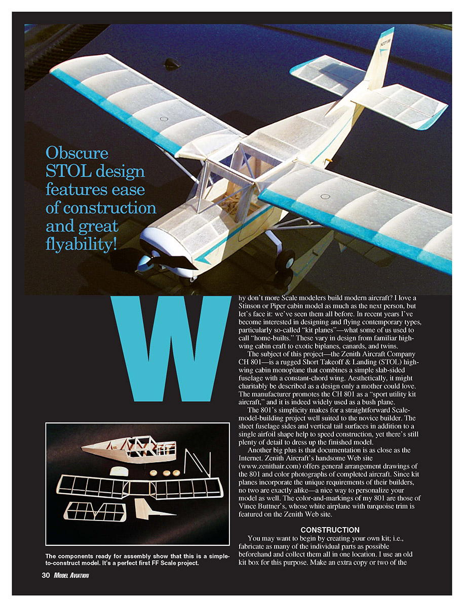
Why don't more scale modelers build modern aircraft? I love a Stinson or Piper cabin model as much as the next person, but we've seen them all before. In recent years I've become interested in designing and flying contemporary types, particularly so-called "kit planes" — what some of us used to call "home-builts." These vary in design from familiar high-wing cabin craft to exotic biplanes, canards, and twins.
The subject of this project — the Zenith Aircraft Company CH 801 — is a rugged Short Takeoff & Landing (STOL) high-wing cabin monoplane that combines a simple slab-sided fuselage with a constant-chord wing. Aesthetically, it might charitably be described as a design only a mother could love. The manufacturer promotes the CH 801 as a "sport utility kit aircraft," and it is indeed widely used as a bush plane.
The 801's simplicity makes for a straightforward scale-model-building project well suited to the novice builder. The sheet fuselage sides and vertical tail surfaces, in addition to a single airfoil shape, help to speed construction, yet there's still plenty of detail to dress up the finished model.
Another big plus is that documentation is as close as the Internet. Zenith Aircraft's website (www.zenithair.com) offers general arrangement drawings of the 801 and color photographs of completed aircraft. Since kit planes incorporate the unique requirements of their builders, no two are exactly alike — a nice way to personalize your model as well. The color-and-markings of my 801 are those of Vince Buttner's, whose white airplane with turquoise trim is featured on the Zenith website.
Specifications
- Type: Free Flight Rubber Sport Scale
- Wingspan: 20 inches
- Power: Two loops 1/8-inch FAI Tan II rubber
- Flying weight: 1 1/4 ounces
- Construction: Balsa sheet and stick
- Covering: Japanese tissue
Construction
You may want to begin by creating your own kit; i.e., fabricate as many of the individual parts as possible beforehand and collect them all in one location. I use an old kit box for this purpose. Make an extra copy or two of the plans so you have patterns to trace or transfer to balsa. This kind of preparation will speed assembly.
The tail surfaces are very easy to make. The vertical tail consists of two pieces of 1/32-inch sheet balsa. The horizontal tail mates a pair of simple sheet wingtips with 1/16- or 3/32-inch strip.
Fuselage:
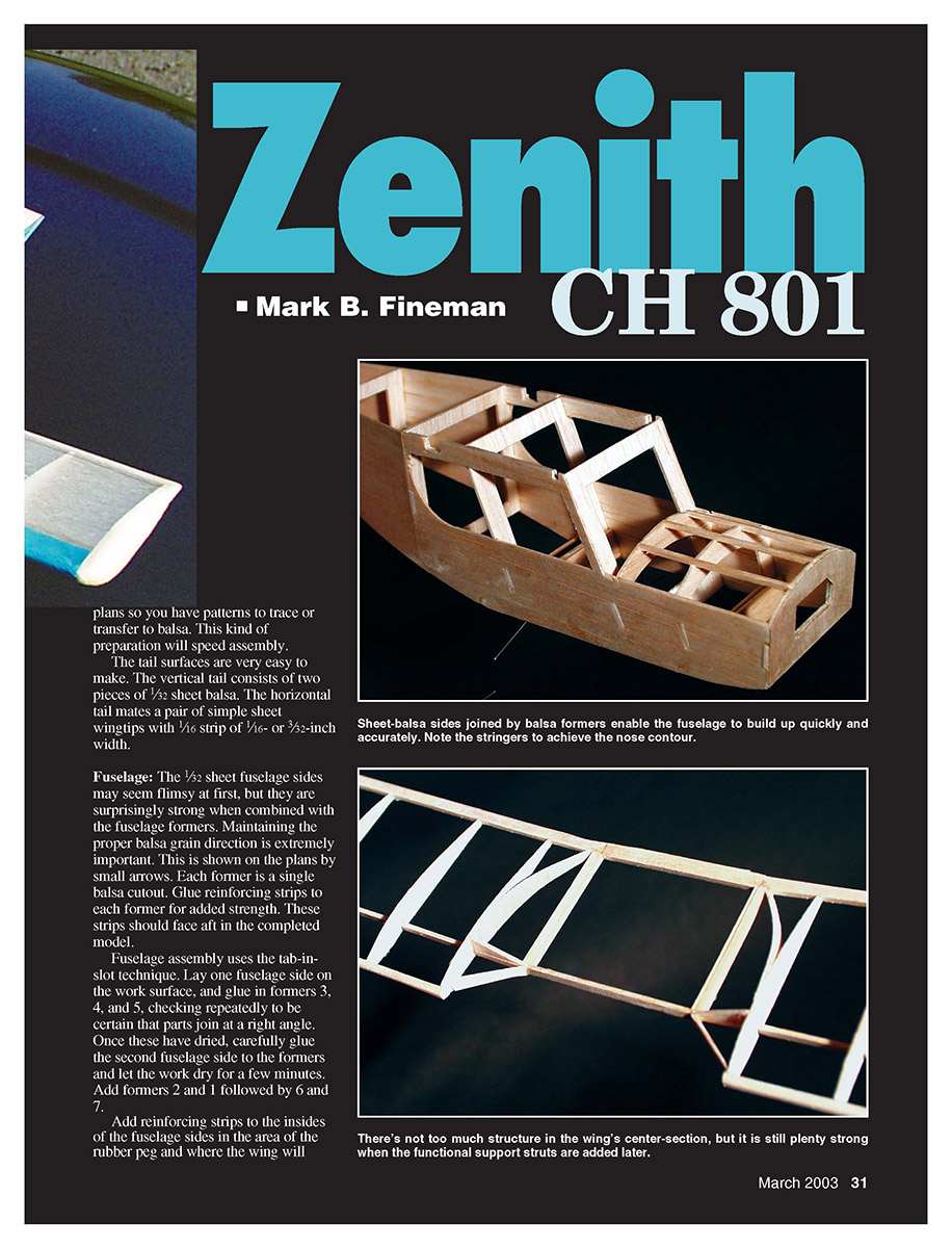
- The 1/32-inch sheet fuselage sides may seem flimsy at first, but they are surprisingly strong when combined with the fuselage formers. Maintaining the proper balsa grain direction is extremely important; this is shown on the plans by small arrows.
- Each former is a single balsa cutout. Glue reinforcing strips to each former for added strength. These strips should face aft in the completed model.
- Fuselage assembly uses the tab-in-slot technique. Lay one fuselage side on the work surface and glue in formers 3, 4, and 5, checking repeatedly to be certain that parts join at a right angle. Once these have dried, carefully glue the second fuselage side to the formers and let the work dry for a few minutes.
- Add formers 2 and 1 followed by 6 and 7. Add reinforcing strips to the insides of the fuselage sides in the area of the rubber peg and where the wing will eventually mate with the fuselage.
- Glue the bent-wire landing gear to formers 4 and 2, and reinforce with simple rectangular balsa doublers. The three 1/16-inch square stringers between formers 1 and 2a complete the job.
Wing:
- The wing panels are built separately and will eventually be joined to the center section. Cut the 1/16 x 1/8-inch wing spar and leading and trailing edges from fairly firm balsa.
- Lay the spar and edge stock directly over the waxed-paper-covered plan, then glue in the ribs and foam or balsa wingtips. A curved riblet joins the inner rib; the curvature is accomplished by running the grain vertically on the riblets. Add the two small triangular formers located nearby.
- When the wing panels have dried thoroughly, remove them from the plans and sand the tips and leading and trailing edges to shape.
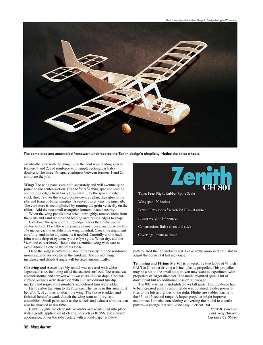
- Lay down the spar and trailing-edge pieces that make up the center section. Place the wing panels against these, and raise the tips 1/8 inch each to establish the wing dihedral. Check alignment carefully and make adjustments if needed.
- Carefully join each joint with a drop of cyanoacrylate (CyA) glue. When dry, add the 1/8-inch round center brace. Handle the assembled wing with care to avoid knocking one of the joints loose.
- Once the wing is covered, it should fit exactly into the reinforced mounting grooves located in the fuselage. The correct wing incidence and dihedral angle will be fixed automatically.
Covering and Assembly
My model was covered with white Japanese tissue, including all of the sheeted surfaces. The tissue was alcohol-shrunk and sprayed with two coats of clear dope. Control-surface outlines were drawn on with a Sharpie-brand fine-tip marker, and registration numbers and colored trim were added.
- Firmly glue the wing to the fuselage. The tissue in this area must be left off to attach the wing; the tissue is added and finished afterward.
- Attach the wing-strut and jury-strut assemblies.
- Small parts, such as the wheels and exhaust shrouds, can also be attached at this time.
- Carefully glue the clear side windows and windshield into place with a gentle application of clear glue, such as RC/56. For a neater appearance, cover the side acetate with a bond-paper window pattern.
- Add the tail surfaces last. Leave some room in the fin slot to adjust the horizontal tail incidence.
Trimming and Flying
My 801 is powered by two loops of 1/8-inch FAI Tan II rubber driving a 6-inch plastic propeller. This propeller may be a bit on the small side, so you may want to experiment with propellers of larger diameter. The model required quite a bit of downthrust but no additional nose or tail weight.
- The 801 was first hand-glided over tall grass. Tail incidence had to be increased until a smooth glide was obtained.
- Under power, it climbs to the left and glides to the right. Flights are stable, usually in the 35- to 45-second range.
- A larger propeller might improve endurance. Converting the model to electric power should be easy to effect and is under consideration.
Mark B. Fineman 1244 Wolf Hill Rd. Cheshire, CT 06410
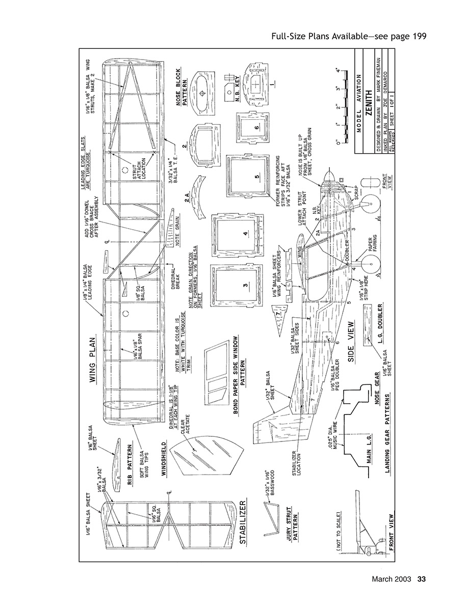
Full-Size Plans Available — see page 199
Wing Plan
- Rib pattern
- Windshield
- Bond paper side window pattern
- Nose block pattern
- Side view
- Front view
- Main L.G.
- Landing gear patterns
- Jury strut pattern
Stabilizer
Transcribed from original scans by AI. Minor OCR errors may remain.

