
Zephyr
The idea of this glider is certainly not original with me, for I have been hand‑tossing Wanderers and the like for some time. Small RC gliders are such a logical evolution.
Zephyr brings together many aspects of modeling. The lightweight construction is similar to that of free‑flight models. It can be hand‑launched into thermals like solid‑balsa gliders. It soars like a high‑performance sailplane. It slope‑soars from a ridge in light‑to‑moderate wind, and it can do aerobatics.
It also can be hand‑towed or launched with a hi‑start. Best of all, it is RC and fun to fly!
I enjoy flying most types of RC models, but the more elaborate they are, the more uptight I get while flying. Not so with Zephyr. There is no anxiety, because there is not so much time and money invested. If it sounds like I am sold on this phase of modeling, you are right.
Advantages of the small silent flier are the absence of noise and the small space requirements. Any empty parking lot or public park can become a flying site—no need to drive miles to the regular flying field. You even can get in a few pitches after work.
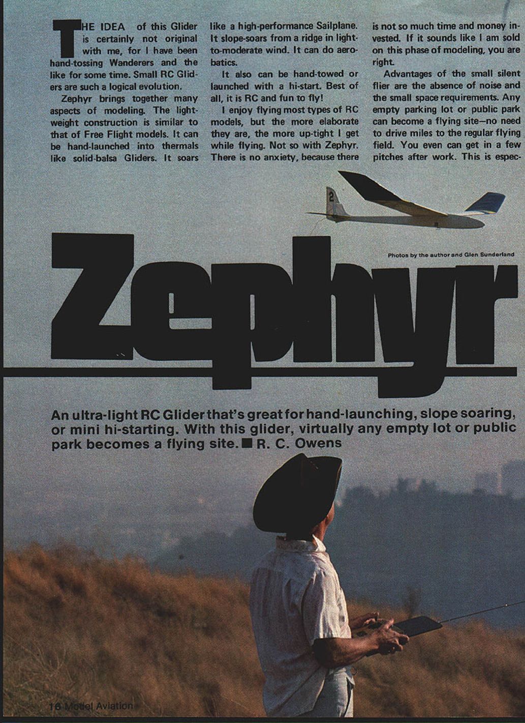
An ultra‑light RC glider that's great for hand‑launching, slope soaring, or mini hi‑starting. With this glider, virtually any empty lot or public park becomes a flying site. — R. C. Owens
DESIGN CONSIDERATIONS
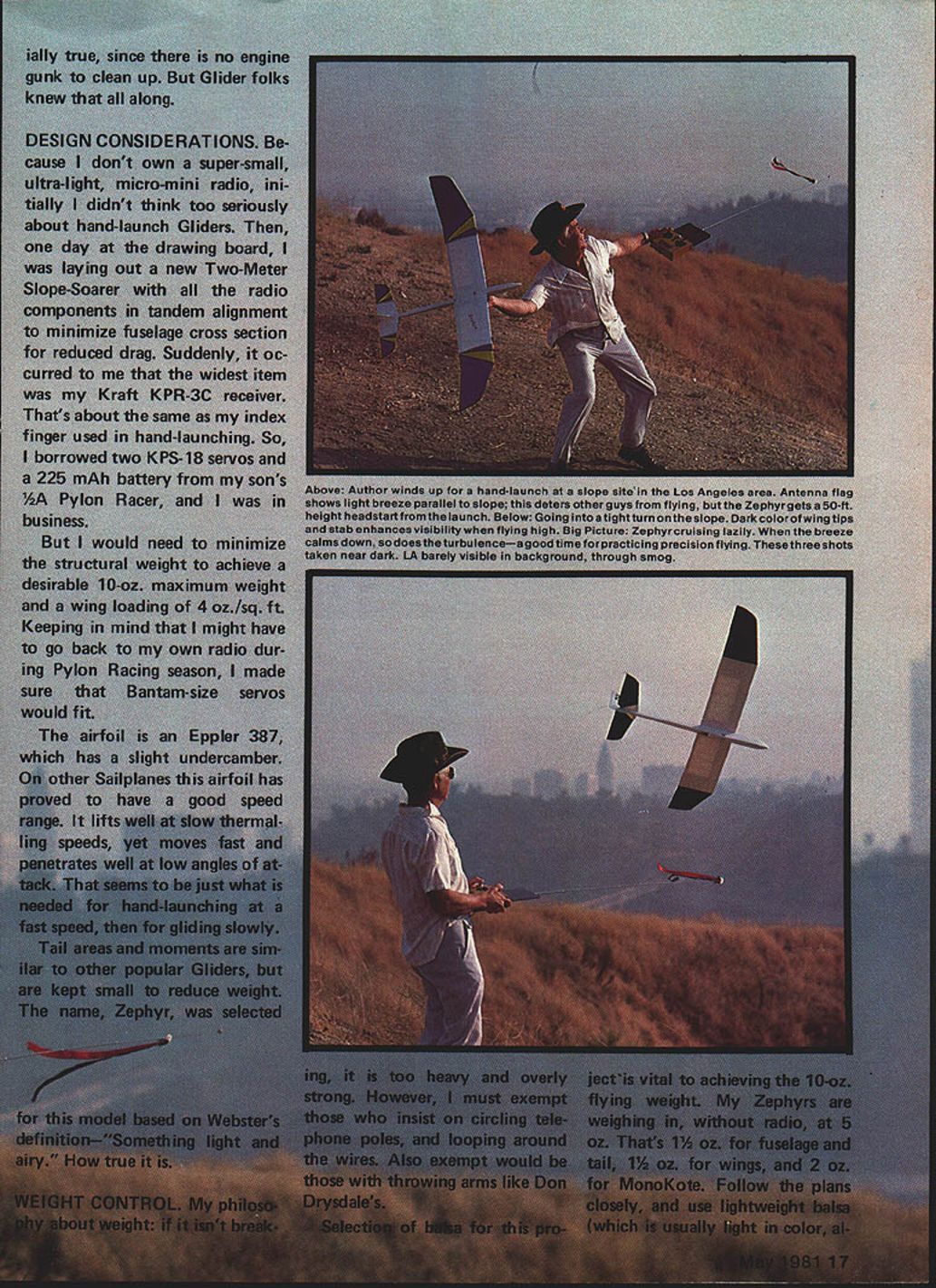
Because I didn't own a super‑small, ultra‑light, micro‑mini radio initially, I didn't think too seriously about hand‑launch gliders. Then, one day at the drawing board, I was laying out a new two‑meter slope‑soarer with all the radio components in tandem alignment to minimize fuselage cross section for reduced drag. Suddenly, it occurred to me that the widest item was my Kraft KPR‑3C receiver. That's about the same as my index finger used in hand‑launching. So, I borrowed two KPS‑18 servos and a 225 mAh battery from my son's 1/2A pylon racer, and I was in business.
But I would need to minimize the structural weight to achieve a desirable 10‑oz. maximum weight and a wing loading of 4 oz./sq. ft. Keeping in mind that I might have to go back to my own radio during pylon racing season, I made sure that bantam‑size servos would fit.
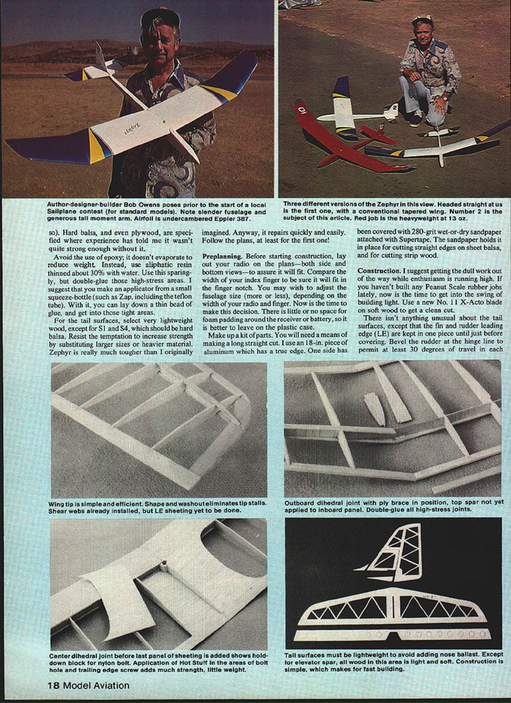
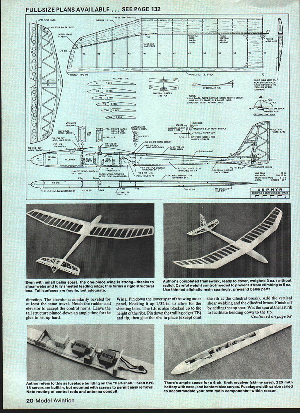
The airfoil is an Eppler 387, which has a slight undercamber. On other sailplanes this airfoil has proved to have a good speed range. It lifts well at slow thermalling speeds, yet moves fast and penetrates well at low angles of attack. That seems to be just what is needed for hand‑launching at a fast speed, then for gliding slowly.
Tail areas and moments are similar to other popular gliders, but are kept small to reduce weight. The name Zephyr was selected for this model based on Webster's definition—"Something light and airy." How true it is.
WEIGHT CONTROL
My philosophy about weight: if it isn't breaking, it is too heavy and overly strong. However, I must exempt those who insist on circling telephone poles and looping around the wires. Also exempt would be those with throwing arms like Don Drysdale's.
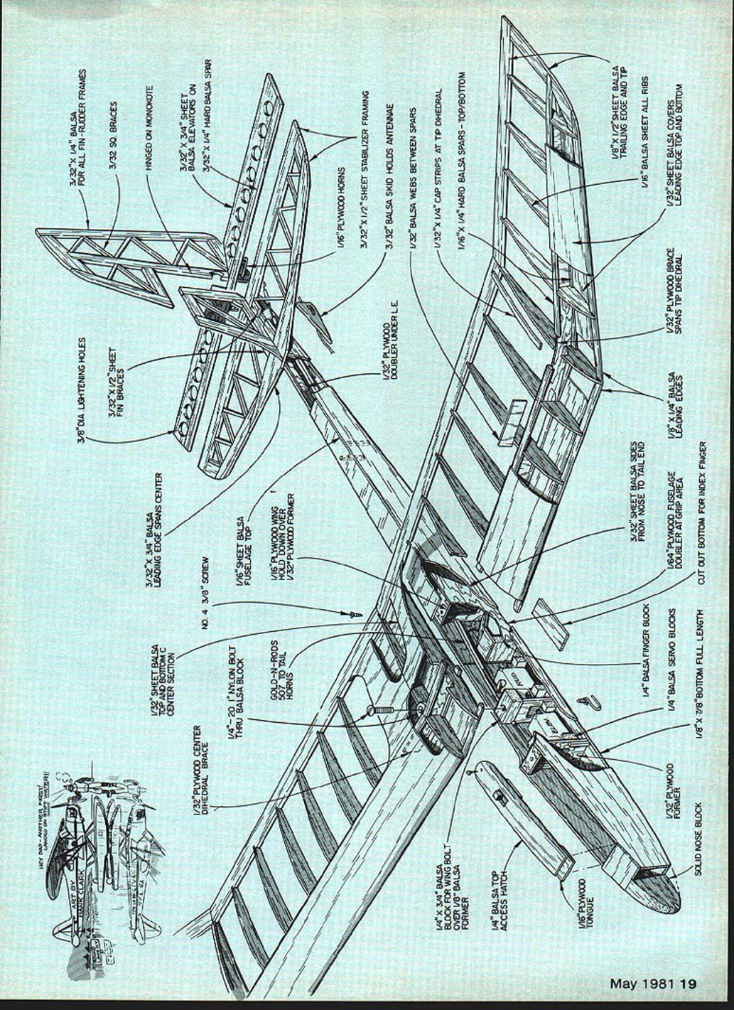
Selection of balsa for this project is vital to achieving the 10‑oz. flying weight. My Zephyrs are weighing in, without radio, at 5 oz. That's 1‑1/2 oz. for fuselage and tail, 1‑1/2 oz. for wings, and 2 oz. for MonoKote. Follow the plans closely, and use lightweight balsa (which is usually light in color, also). Hard balsa, and even plywood, are specified where experience has told me it wasn't quite strong enough without it.
Avoid the use of epoxy; it doesn't evaporate to reduce weight. Instead, use aliphatic resin thinned about 30% with water. Use this sparingly, but double‑glue those high‑stress areas. I suggest that you make an applicator from a small squeeze‑bottle (such as Zap, including the Teflon tube). With it, you can lay down a thin bead of glue and get into those tight areas.
For the tail surfaces, select very lightweight wood, except for S1 and S4, which should be hard balsa. Resist the temptation to increase strength by substituting larger sizes or heavier material. Zephyr is really much tougher than I originally imagined. Anyway, it repairs quickly and easily. Follow the plans, at least for the first one!
Preplanning
Before starting construction, lay out your radio on the plans—both side and bottom views—to assure it will fit. Compare the width of your index finger to be sure it will fit in the finger notch. You may wish to adjust the fuselage size (more or less), depending on the width of your radio and finger. Now is the time to make this decision. There is little or no space for foam padding around the receiver or battery, so it is better to leave on the plastic case.
Make up a kit of parts. You will need a means of making a long straight cut. I use an 18‑in. piece of aluminum which has a true edge. One side has been covered with 280‑grit wet‑or‑dry sandpaper attached with Supertape. The sandpaper holds it in place for cutting straight edges on sheet balsa and for cutting strip wood.
Construction
I suggest getting the dull work out of the way while enthusiasm is running high. If you haven't built any Peanut Scale rubber jobs lately, now is the time to get into the swing of building light. Use a new No. 11 X‑Acto blade on soft wood to get a clean cut.
There isn't anything unusual about the tail surfaces, except that the fin and rudder leading edge (LE) are kept in one piece until just before covering. Bevel the rudder at the hinge line to permit at least 30 degrees of travel in each direction; elevator similarly beveled.
Wing
Pin down the lower spar of the outer wing panel at the dihedral break, blocking it up 1/32 in. to allow for the sheeting later. The LE is also blocked up to the height of the ribs. Pin down the trailing edge (TE) and tip, then glue the ribs in place (omit the rib at the dihedral break where noted). Add the vertical shear webbing between spars at the tip dihedral and the dihedral brace. Finish off by adding the top spar. Wet the spar at the last rib to facilitate bending down to the tip.
Build the inner wing panels in the same manner, but join the outer panel to the inner panel just before adding the top spar. Turn the plans over, and build the opposite wing.
Join the right and left wing halves by first adding the center dihedral brace. Then add the bolt block. The center rib is cut and fitted between the LE and spar, then between the block and TE.
Add the LE sheeting in the following sequence: lower inner panels, lower outer panels, then the upper inner panels and upper outer panels. Next, add the lower center panel and the upper center panels.
Sand it, weigh it, and sand some more. Since the sheeting is usually warped on the edges, you must trim off a slice with that straightedge mentioned earlier before trying to glue it to the wing.
The one‑piece wing, with shear webs and fully sheeted leading edge, forms a rigid structural box and is strong. Tail surfaces are fragile until completed; the framework, ready to cover, weighed 3 oz. without radio.
Fuselage
The fuselage will be built up on the "half‑shell," so to speak, as there is insufficient space down inside the fuselage to do much work after it is boxed in. Everything possible will be completed prior to installing the left side of the fuselage.
Attach doublers (F7 and F9) to the inside of each fuselage side (F2). Use Hot Stuff, Zap, or Jet, and make one left and one right side. Throughout these instructions I will refer to Hot Stuff, but you can take your pick of any cyanoacrylate glue.
Lay the right side over the side view of the plans, and glue in place the nose block (F1) and formers (F3, F4A, F4B, F5). The fuselage tapers between F3 and F5, so the width of all the cross members must be carefully measured to achieve a good fit when the left side is put in place. Before gluing these parts in place, lay a straightedge across F3 and F4 or F4 and F5—to be sure you have a good fit.
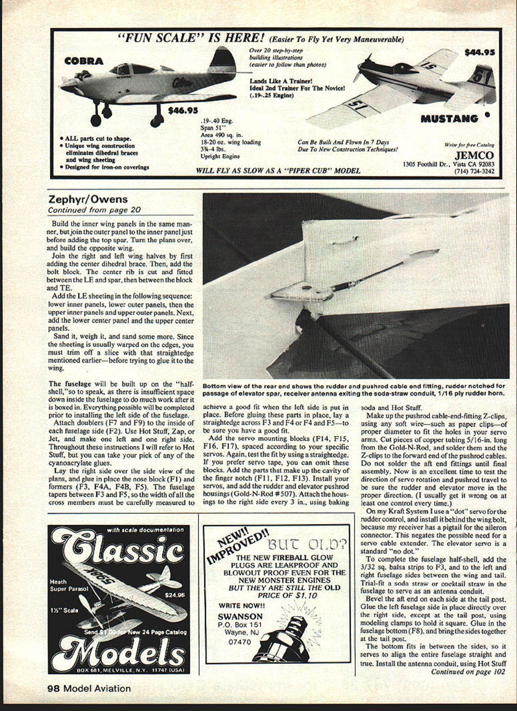
Add the servo mounting blocks (F14, F15, F16, F17), spaced according to your specific servos. Again, test the fit by using a straightedge. If you prefer servo tape, you can omit these blocks. Add the parts that make up the cavity of the finger notch (F11, F12, F13). Install your servos, and add the rudder and elevator pushrod housings (Gold‑N‑Rod #507). Attach the housings to the right side every 3 in., using baking soda and Hot Stuff.
Make up the pushrod cable‑end‑fitting Z‑clips using any soft wire—such as paper clips—or proper diameter wire to fit the holes in your servo arms. Cut pieces of copper tubing 5/16 in. long from the Gold‑N‑Rod, and solder them and the Z‑clips to the forward end of the pushrod cables. Do not solder the aft end fittings until final assembly. Now is an excellent time to test the direction of servo rotation and pushrod travel to be sure the rudder and elevator move in the proper direction. (I usually get it wrong on at least one control every time.)
On my Kraft system I use a "dot" servo for the rudder control, and install it behind the wing bolt, because my receiver has a pigtail for the aileron connector. This negates the possible need for a servo cable extender. The elevator servo is a standard "no dot."
To complete the fuselage half‑shell, add the 3/32 sq. balsa strips to F3 and to the left and right fuselage sides between the wing and tail. Trial‑fit a soda straw or cocktail straw in the fuselage to serve as an antenna conduit.
Bevel the aft end on each side at the tail post. Glue the left fuselage side in place directly over the right side, except at the tail post, using modeling clamps to hold it square. Glue in the fuselage bottom (F8), and bring the sides together at the tail post.
The bottom fits in between the sides, so it serves to align the entire fuselage straight and true. Install the antenna conduit using Hot Stuff and baking soda, and a few turns of sewing thread if necessary. Add the top hatch hold‑down (F6), the wing TE hold‑down (F19), and the fuselage top sheeting.
Temporarily install the wing, using the nylon bolt; align the wing square with the fuselage, and install the trailing edge screw. Glue F19 to the top hatch (F20), and carve the aft edge to fit the wing upper surface. While the wing is in place, place a straightedge on the fuselage tail‑rest to check the dihedral alignment between the wing and horizontal tail.
Remove, shape, and sand the nose block, and sand the fuselage corners. If you have been building nothing but large models, you will be amazed at how fast these small jobs go together.
Covering
I use MonoKote because of its strength‑to‑weight ratio. But do spend a little extra time in planning and executing a multi‑colored covering scheme.
I have standardized on the scheme shown in the photos, which is white with metallic‑blue tips and a splash of yellow. More important: on the bottom I omit the yellow and use blue on the undersides of the wing tips and horizontal stab/elevator. This gives excellent visibility in a variety of sky conditions.
Zephyr gets up and nearly out of sight in a hurry, so color contrast on the lower surfaces is helpful in keeping it in view longer. This arrangement provides three points of reference which helps in orienting the direction of flight and the pitch (climb or dive) attitude.
Omit covering where the tail surfaces are glued on. Hinge the rudder and elevator with a strip of MonoKote at least 1 in. wide—attached on the side opposite the beveled edge. Leave about 1/16 in. space between the fixed and hinged portions to allow freedom of movement. After the MonoKote is tightened to the wings, attach it to the undercambered ribs.
Final assembly
Install your radio switch in the top hatch (this way you will not leave the hatch at home) or on the left fuselage side just ahead of the wing and above the receiver. I made a lightweight switch harness, using a tiny audio slide switch (these switches are not suitable for power planes, since they are subject to intermittent operation due to vibration). Leave out the charging jack; keep it connected to the charger (avoid carrying around extra weight).
Again, install the wing, then glue the horizontal tail in place—while carefully aligning it with the wing as viewed from the rear. Also note that the slot in the stab to receive the fin must be centered on the fuselage and aimed straight‑away at the wing bolt. Epoxy (yes, this is the first time I have called for epoxy) the rudder and elevator horns in place.
Terminate the cable pushrod Z‑clips, but first turn on the radio, and center the trim knobs. The rudder and elevator surfaces must be in the neutral positions when you solder the end fittings in place. If flight trim adjustments are necessary, longer or shorter Z‑clips can be made up for the necessary correction. Operate the servos full travel to be sure there is no binding. Now, make sure the center‑of‑gravity (CG) is balanced per the plans, and get rid of any warps; 1/8 in. washout at the tips is good.
FLYING
Thermal or slope, hand‑launch or mini hi‑start, take your pick! Initially, I suggest you go over to a local park with a baseball diamond and a grass outfield. Start with some gentle tosses, adding a little muscle as you build confidence. Also, start to aim it a little higher, and soon you will be tossing it up at about 60 degrees and getting 50 to 60 feet of altitude at the top of the climb.
I have the best success with a stiff‑arm toss. More of a sling, getting the waist and shoulder into it, keeps from throwing your arm away. It's just like tossing hand grenades back in WWII. After you have the throwing down, and can push it over at the top of the climb without stalling, walk over to the downwind edge of the bare infield of the baseball field. If the sun is out (heating the ground), and the wind is not blowing, you just might pick up a little thermal. If the breeze is blowing, it is best not to circle, but to do S‑turns—always turning into the wind until you get lift. If the turns are too tight, you will create lots of wing lift, but lots of drag at the same time. Keep the turns as shallow as practical, so that the wing will contribute to altitude gain and not just to going around in circles.
I had always considered the desert a great place for thermals, but it isn't necessarily so! The desert floor is just too regular and uniform—that is, unless you can find a place that has a few ridges or barren spots.
I have relatives who live in the desert, so on the first visit after finishing the prototype Zephyr, I took it along. The morning was hot, clear, and calm, but I couldn't get anything more than a few wing wiggles and an occasional bump of lift. Then I spotted a little ditch which somehow had air due to a water pipe. The foot‑high ridge and bare dirt was all it took to start a bubble of warm air on its way up. I was able to work the small amount of lift generated there for several minutes at a time. But that is tiring work, because you have to put the model exactly in the right spot all the time.
Just for kicks, I made a mini hi‑start, using 25 ft of 3/16‑in. flat rubber and 100 ft of 10‑lb‑test fishing line, with an old antenna ribbon as a streamer in place of the more usual parachute. The optional tow hook shown on the plan worked very well, and yielded better results in the desert than hand‑launching. I am sure it would be even better with twice the length of rubber and line.
Maybe I am just lazy, but slope soaring is much more to my liking, especially on those late lazy afternoons when the wind is down to a whisper and just a few gliders are left on the slope—just barely scratching out a flight. Zephyr really shines, and it is always the last plane to be forced to land. It can be tossed up 50 ft above the ridge, where just the gentlest of breezes will permit several passes.
Balance is very important even for a gentle, forgiving little bird, not only for slow flight but for hand‑launching. The speed range is quite broad when hand‑launching. It is easily doing 50 mph at launch as it leaves the hand, and about 10 mph in light lift. How can it be trimmed for both conditions?
If you get the balance at the correct place, it will be trimmed for both conditions and anything in between. When you throw it up, it should go straight as a rock. If it zooms up, you have it too nose‑heavy. If it is too tail‑heavy, it will tend to arc downward in a slight dive. In both cases, this assumes you have the model adjusted for a relatively slow hands‑off glide. The extra nose weight causes extra up‑elevator trim just to keep the model level during slow flight. When you throw it hard, it is above the trim speed, and the up‑elevator trim causes the nose to pull up.
You can also test this same thing while gliding higher up. Start with a slow‑trimmed glide. Gradually push the nose down, and hold the control stick in that same position while the model builds up speed. If it tends to pull out of the dive, it is too nose‑heavy. If the dive steepens, it is tail‑heavy. With correct balance, it should continue in the same diving attitude that it started.
At the correct balance point, Zephyr will do loops, rolls, and inverted flight. But don't expect inverted flight with that undercambered airfoil to be as good as upright flight. With a decent wind on the slope, you should be able to maintain altitude when inverted.
When you have Zephyr mastered, then make the control surfaces more sensitive (more travel). The more the better for real fun.
Transcribed from original scans by AI. Minor OCR errors may remain.

