
Zephyr 1100
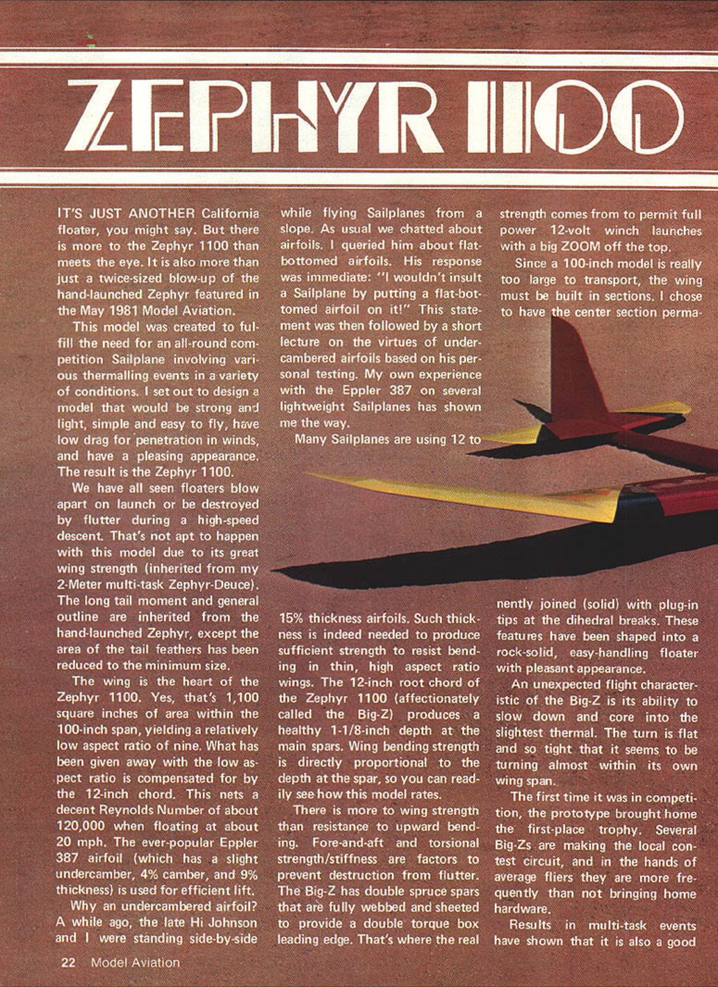
It's just another California floater, you might say. But there is more to the Zephyr 1100 than meets the eye. It is also more than just a twice-sized blow-up of the hand-launched Zephyr featured in the May 1981 Model Aviation.
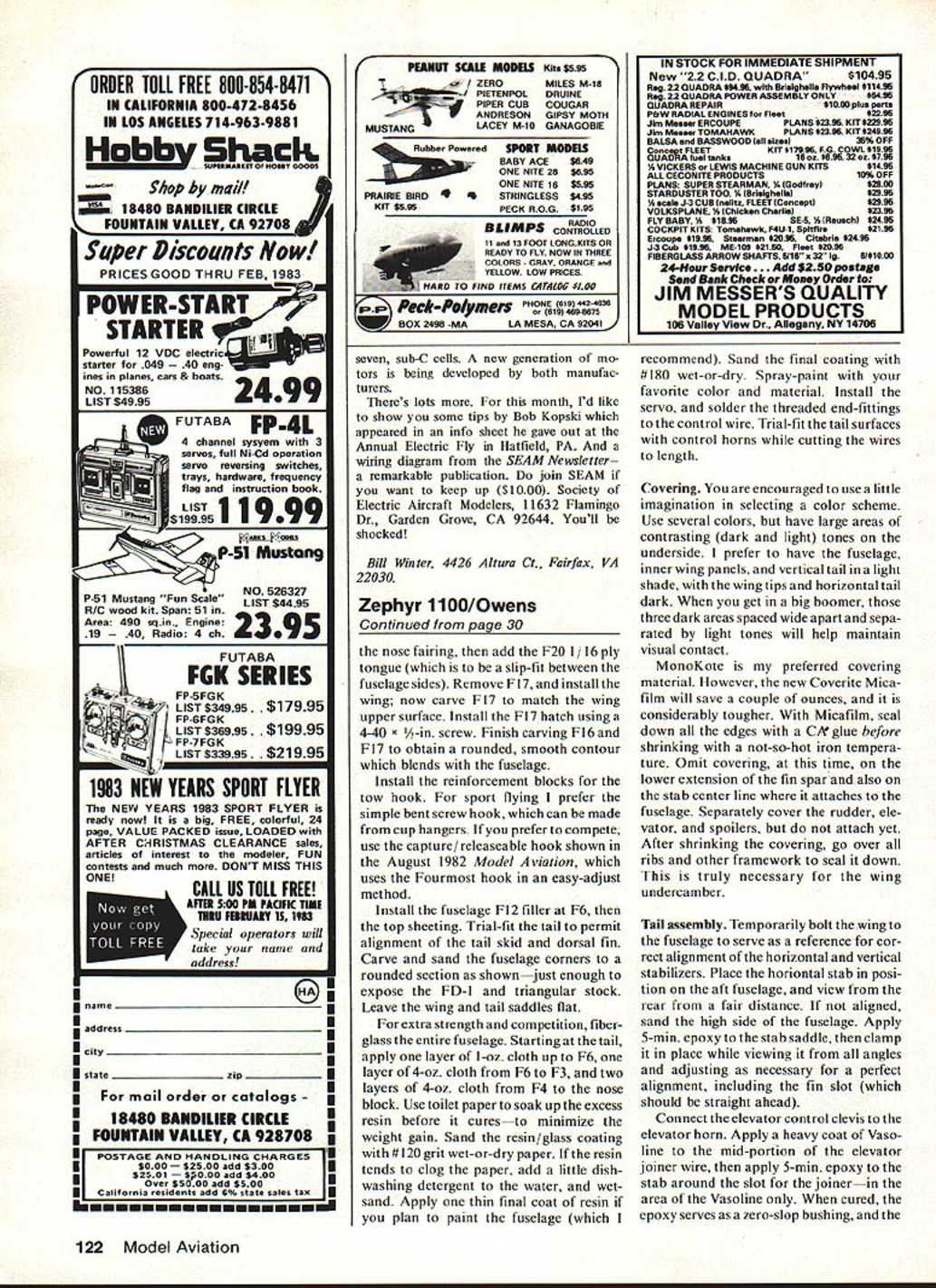
This model was created to fulfill the need for an all-round competition sailplane for various thermalling events in a variety of conditions. The design goals were: strong and light, simple and easy to fly, low drag for penetration in winds, and a pleasing appearance. The result is the Zephyr 1100 (the "Big-Z").
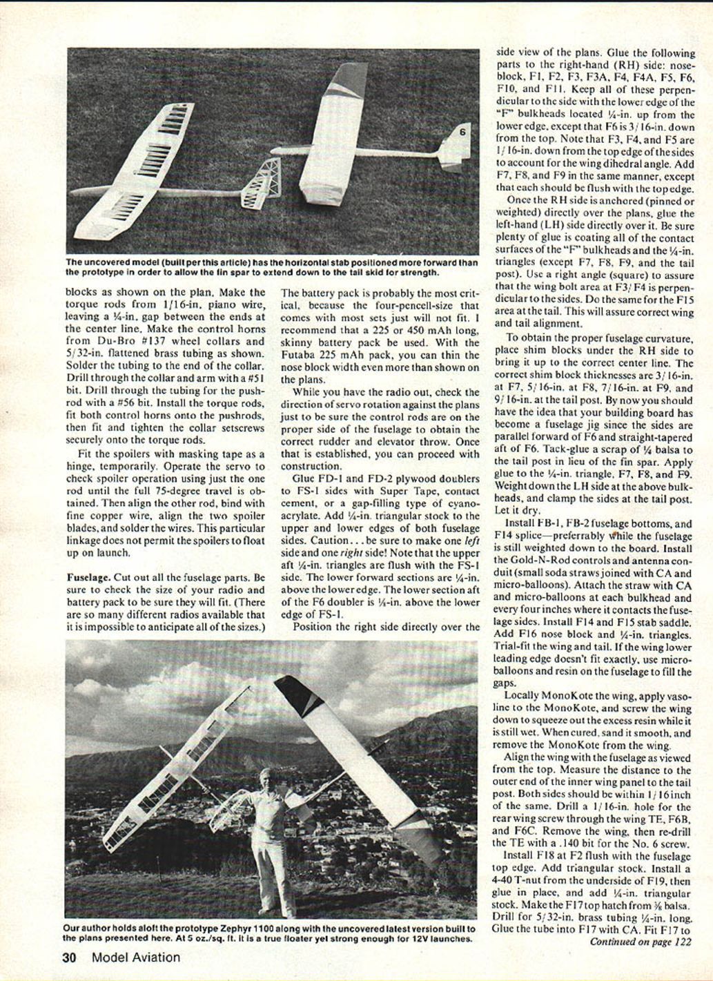
The Big-Z's wing strength (inherited from my 2-meter multi-task Zephyr-Deuce) reduces the chance of launch failure or flutter-related destruction. The long tail moment and general outline are inherited from the hand-launched Zephyr, but the tail surface areas have been reduced to the minimum consistent with good static stability.
The wing is the heart of the Zephyr 1100: 1,100 sq. in. area within a 100 in. span, yielding an aspect ratio of about 9. The 12 in. chord produces a Reynolds number around 120,000 when floating at roughly 20 mph. The Eppler 387 airfoil (slight undercamber, ~4% camber, 9% thickness) was chosen for efficient lift.
Why an undercambered airfoil? The late Hi Johnson strongly favored undercambered sections from his testing; my own experience with the Eppler 387 on several lightweight sailplanes confirmed its suitability.
Wing thickness of 12–15% is common to provide bending strength in thin, high-aspect wings; the Zephyr's 12 in. root chord yields about 1-1/8 in. depth at the main spars. Wing bending strength is proportional to spar depth, so this contributes to a robust structure.
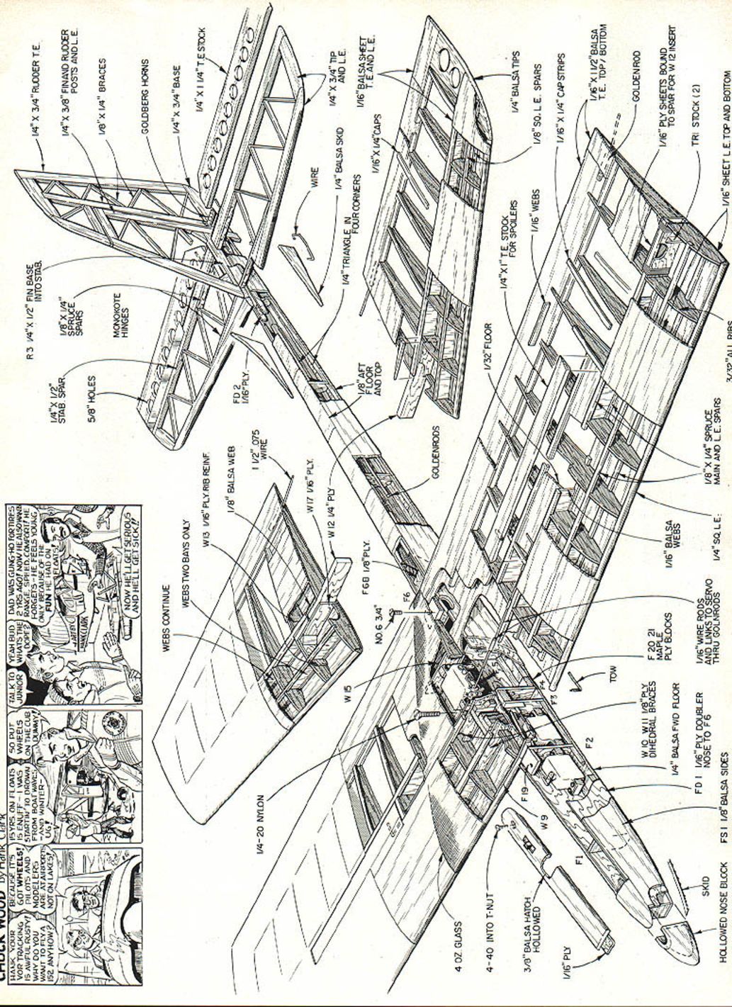
Fore-and-aft and torsional stiffness are also critical to prevent flutter. The Big-Z uses double spruce spars that are fully webbed and sheeted to form a double torque-box leading edge. That construction allows full-power 12-volt winch launches with a big zoom off the top.
Because a 100 in. model is large for transport, the wing is built in sections: a permanently joined center section with plug-in tips at the dihedral breaks. The Big-Z cores slowly into light thermals with a very flat, tight turn that can seem to turn almost within its own wingspan. Competition results have been excellent; prototypes have won first place in their first outing, and several examples are consistently successful in local contests.
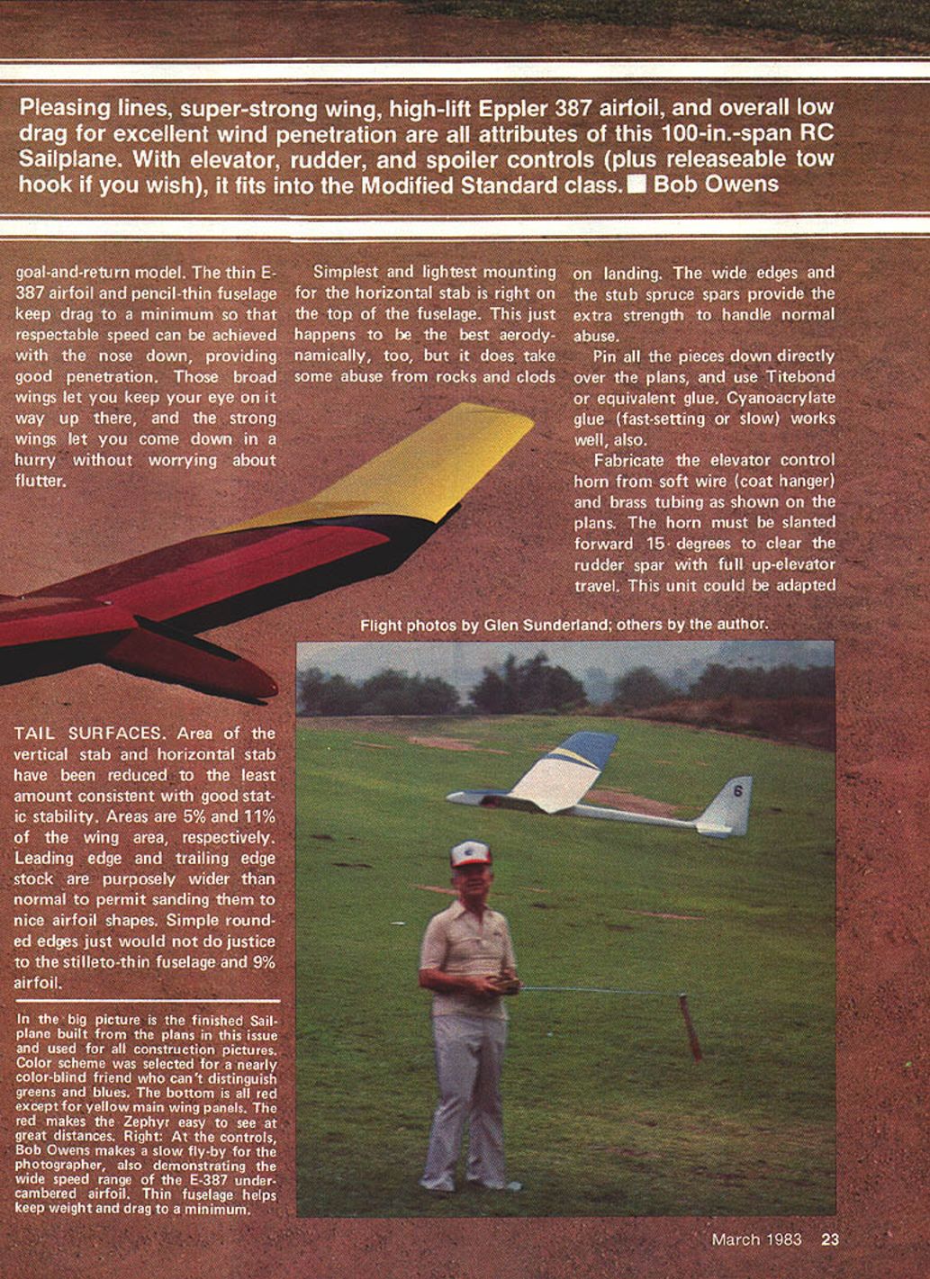
Results in multi-task events show the Zephyr 1100 is also a good goal-and-return model. The thin Eppler 387 airfoil and pencil-thin fuselage keep drag low for good penetration when flown nose-down. The broad wings remain visible at altitude, and the strong wing construction allows rapid descents without worrying about flutter.
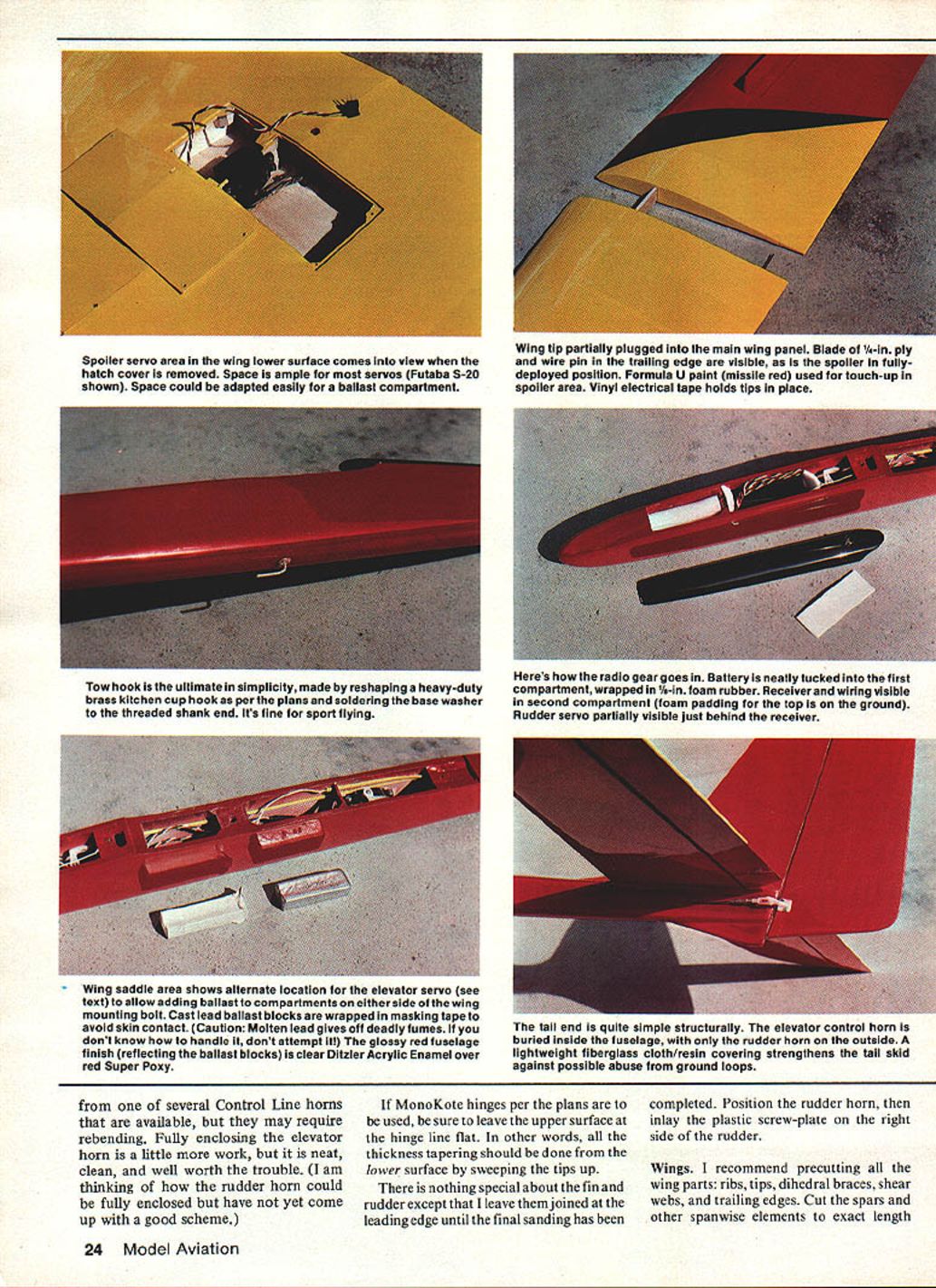
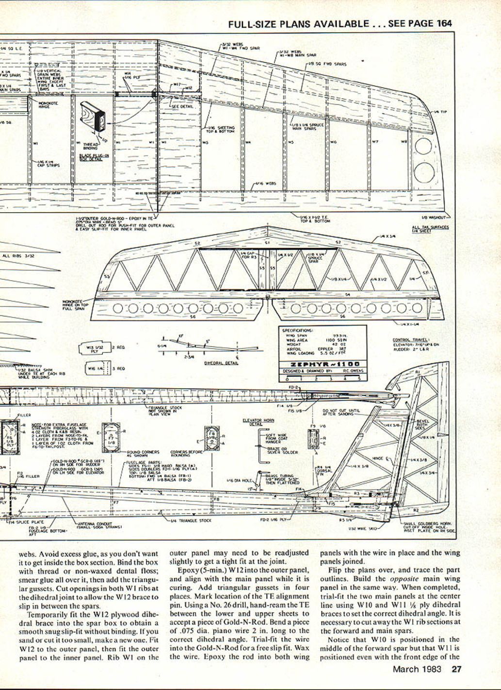
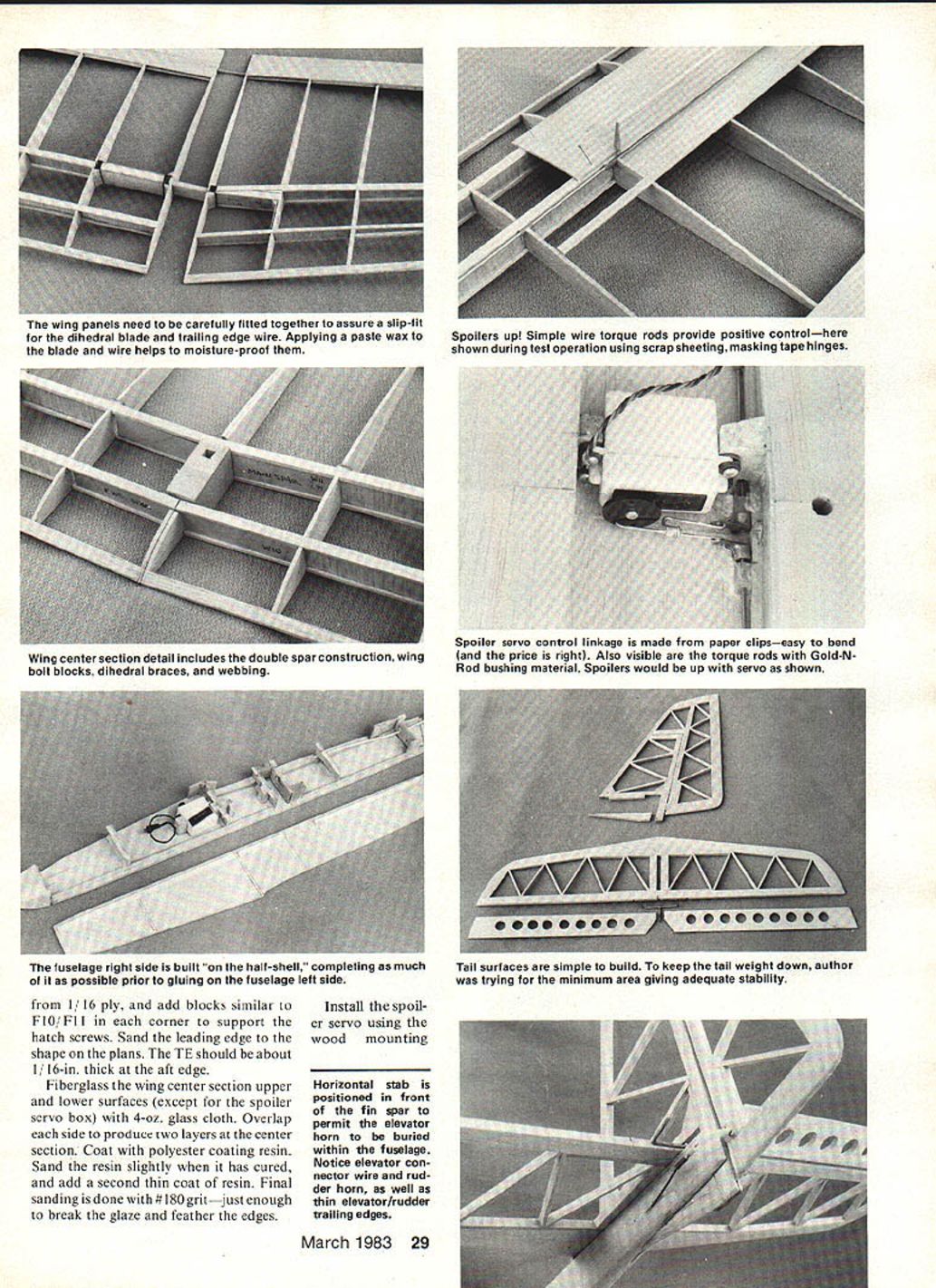
Simplest and lightest horizontal stab mounting is on top of the fuselage — aerodynamically best but exposed to landing abuse. Wide edges and stub spruce spars provide extra strength. Use Titebond or equivalent glue; cyanoacrylate (fast- or slow-setting) also works well.
Fabricate the elevator control horn from soft wire (coat hanger) and brass tubing as shown on the plans. The horn must be slanted forward 15° to clear the rudder spar with full up-elevator travel. This unit could be adapted from one of several control-line horns available, but they may require rebending. Fully enclosing the elevator horn is neater and worth the extra work.
If MonoKote hinges are used per the plans, leave the upper surface at the hinge line flat; do thickness tapering from the lower surface by sweeping the tips up. The fin and rudder are simple; leave them joined at the leading edge until final sanding. Position the rudder horn and inlay the plastic screw plate on the right side of the rudder.
Tail Surfaces
Area of the vertical and horizontal stabs has been reduced to the least amount consistent with good static stability: about 5% and 11% of the wing area, respectively. Leading-edge and trailing-edge stock are purposely wider than normal to permit sanding to slim, airfoil-like shapes rather than simple rounded edges. This detail complements the stiletto-thin fuselage and the 9% airfoil.
Tail surfaces are simple to build. Keep tail weight low while providing adequate stability. Install the elevator and rudder hardware per the plans (see torque-rod and horn details below).
- Make torque rods from 1/16-in. piano wire, leaving a 1/4-in. gap between the ends at the centerline.
- Make control horns from Du-Bro #137 wheel collars and 5/32-in. flattened brass tubing; solder the tubing to the collar end, drill the collar and arm with a #51 bit, drill the tubing for the pushrod with a #56 bit.
- Install torque rods, fit control horns, and tighten collar setscrews securely.
- If enclosing horns, consider fabricating fully enclosed housings for neatness. (Author has not finalized a scheme for the rudder horn enclosure.)
Spoilers: Temporarily fit spoilers using masking tape as hinges and Gold-N-Rod/.075-in. piano wire bushings as described in the wing construction. When satisfied with operation, finalize the linkage. The linkage described does not permit spoilers to float up on launch.
Wings
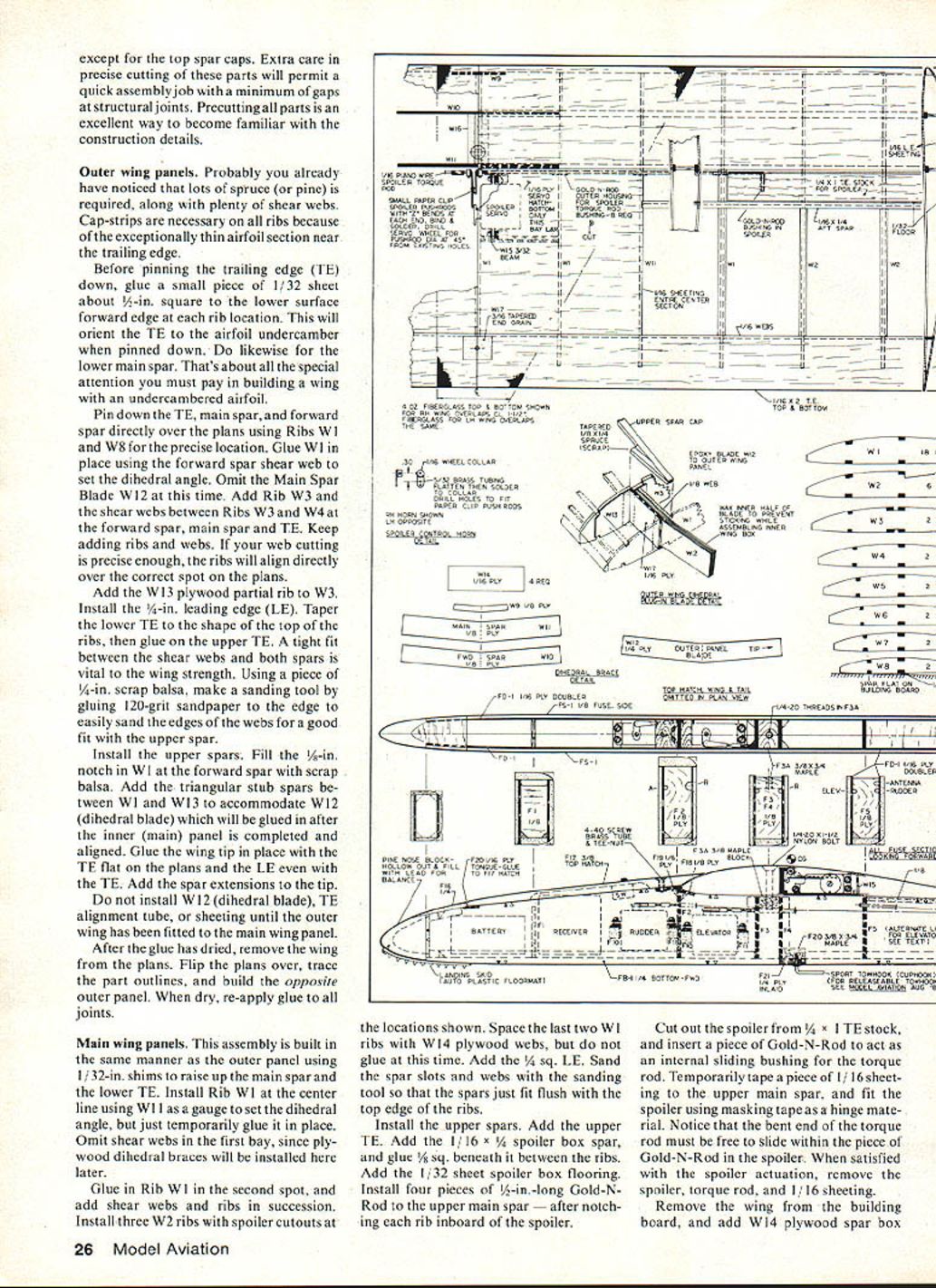
Precut all wing parts: ribs, tips, dihedral braces, shear webs, spars, and trailing edges. Cut spars and spanwise elements to exact length. Cap strips are necessary because the airfoil is exceptionally thin near the trailing edge.
Before pinning the trailing edge (T.E.) down, glue a small piece of 1/32-in. sheet (about 1/4 in. square) to the lower surface at the forward edge of each rib location to orient the undercambered airfoil when pinned. Do likewise for the lower main spar.
Outer wing panels
- Use lots of spruce (or pine) and plenty of shear webs.
- Pin down the T.E., main spar, and forward spar directly over the plans using ribs W1 through W8 in their precise locations. Glue W1 in place using the forward spar and shear web; set the dihedral angle. Omit the main-spar dihedral blade (W12) at this time.
- Add rib W12, then rib W3, and install shear webs between ribs W3 and W4, the forward spar, main spar, and T.E. Keep adding ribs and shear webs as web stock is cut.
- Add the W13 plywood partial rib to W3 and install the 1/4-in. leading edge (L.E.).
- Taper the lower T.E. to match the top of the ribs, then glue on the upper T.E.
- Ensure a tight fit between shear webs and both spars. Use a 1/4-in. scrap balsa sanding tool with 120-grit glued to the edge to sand web edges for a good fit with the upper spar.
- Install upper spars. Fill the 1/8-in. notch in W1 at the forward spar with scrap balsa. Add triangular stub spars between W1 and W13 to accommodate W12 (dihedral blade) later.
- Glue the wing tip in place with the T.E. flat on the plans and the L.E. even with the T.E. Add the spar extensions to the tip.
- Do not install W12, the T.E. alignment tube, or sheeting until the outer wing has been fitted to the main wing panel.
- After glue is dry, remove the wing from the plans, flip plans and trace part outlines, then build the opposite outer panel. When dry, reapply glue to all joints.
Main wing panels
- Build in the same manner as outer panels, using 1/32-in. shims to raise the main spar and the lower T.E.
- Install rib W1 at the centerline using W11 as a gauge to set dihedral — temporarily glue it in place. Omit shear webs in the first bay; plywood dihedral braces will be installed later.
- Glue in the second W1, then add shear webs and ribs in succession. Install three W2 ribs with spoiler cutouts at the locations shown on the plans. Space the last two W1 ribs with W14 plywood webs but do not glue them yet.
- Add the 1/4-sq. L.E. Sand spar slots and webs so spars fit flush with top edge of ribs.
- Install upper spars, add upper T.E., add 1/16 x 1/4 spoiler-box spar, and glue 1/8-sq. beneath it between ribs. Add 1/32-in. sheet spoiler-box flooring.
- Install four pieces of 1/4-in.-long Gold-N-Rod to the upper main spar after notching each rib inboard of the spoiler.
- Make spoiler from 1/4 x 1 T.E. stock and insert Gold-N-Rod as an internal sliding bushing for the torque rod. Temporarily tape 1/16-in. sheeting to the upper main spar and fit the spoiler using masking tape as hinge material. Ensure the torque-rod bent end can slide in the Gold-N-Rod.
- Remove spoiler, torque rod, and 1/16-in. sheeting when satisfied.
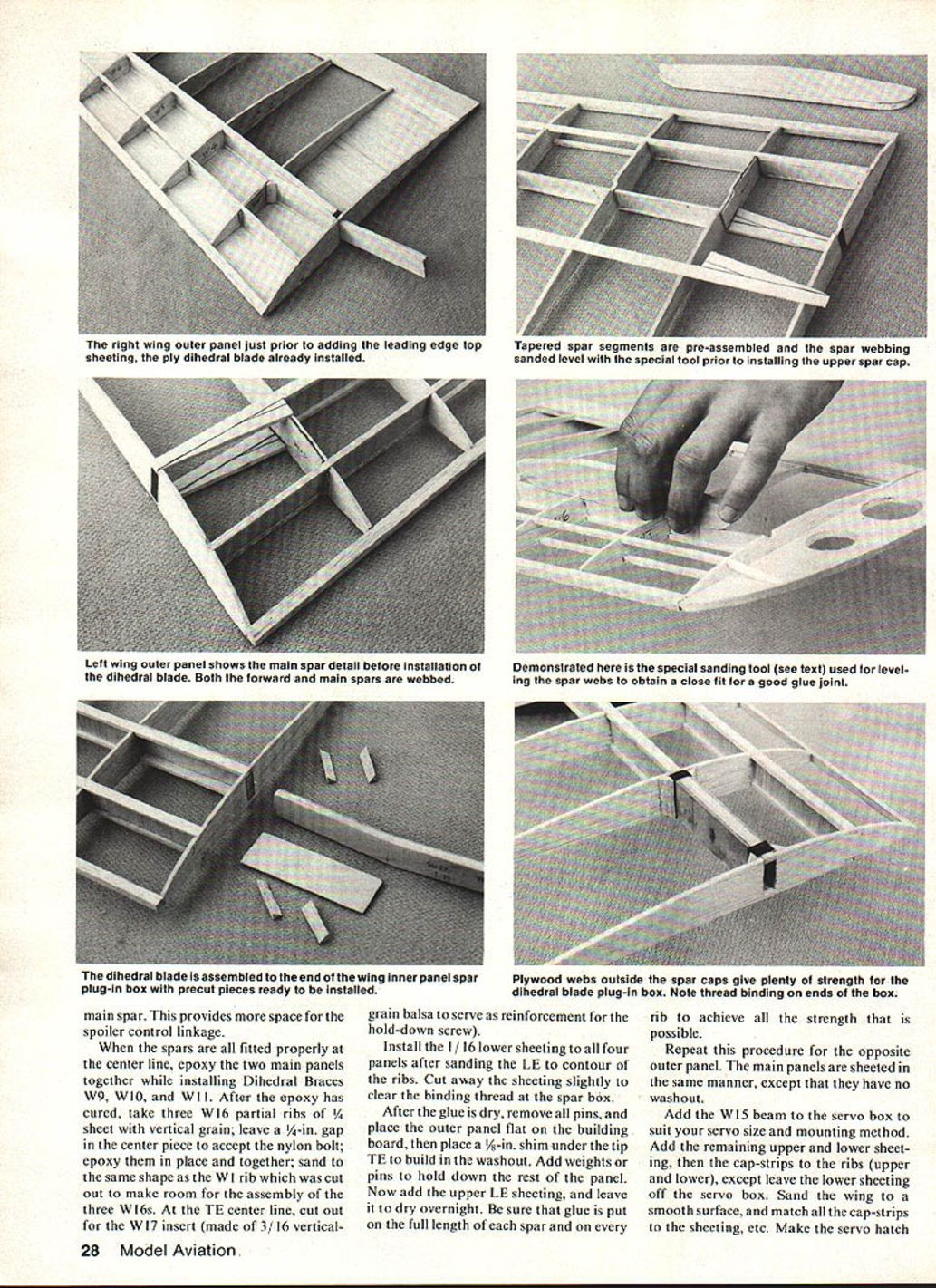
- Add W14 plywood spar box to each main panel and glue in place. Avoid excess glue inside the box. Bind the box with thread or non-waxed dental floss, smear glue over it, then add triangular gussets.
- Cut openings in both W1 ribs at the dihedral joint to allow W12 brace to slip between spars.
- Temporarily fit W12 plywood dihedral brace into the spar box for a snug slip-fit. Fit W12 to the outer panel, then fit outer panel to inner panel; adjust W1 as needed.
- Epoxy (5-min.) W12 into the outer panel and align with the main panel while curing. Add triangular gussets in four places.
- Mark TE alignment-pin location; hand-ream the TE between lower and upper sheets to accept Gold-N-Rod. Bend .075-in. dia. piano wire about 2 in. long to the correct dihedral angle; trial-fit into Gold-N-Rod for free slip fit, wax the wire, and epoxy the rods into both wing panels with the wire in place, joining panels.
- Build the opposite main panel the same way. Trial-fit two main panels at the centerline using W10 and W11 1/8-ply dihedral braces to set dihedral. Cut away W1 rib sections at forward and main spars as necessary.
- Epoxy dihedral braces (W9, W10, W11) in place and join main panels. After curing, epoxy three W16 partial ribs (1/4-in. sheet, vertical grain) in place with a 1/8-in. center gap to accept the nylon bolt; sand them to shape. Cut out for W17 insert (3/16-in. vertical-grain balsa) at the T.E. centerline for hold-down screw reinforcement.
- Install 1/16-in. lower sheeting to all four panels after sanding the L.E. to rib contours. Cut sheeting slightly to clear the binding thread at the spar box.
- After glue dries, remove pins, place outer panel flat on the board with a 3/8-in. shim under the T.E. to build washout; add weights/pins to hold panel. Add upper L.E. sheeting and leave to dry overnight. Ensure glue is applied along full length of each spar and on every rib.
- Repeat for opposite outer panel. Main panels sheet similarly but without washout.
- Add W15 beam to the servo box sized for your servo. Add the remaining upper and lower sheeting, then cap-strips to ribs (upper and lower), except leave lower sheeting off the servo box. Sand wing to smooth surface and match cap-strips.
- Make servo hatch from 1/16-in. ply and add blocks similar to F10/F11 in each corner to support hatch screws. Sand L.E. to the plan shape; T.E. aft edge should be about 1/16 in. thick.
- Fiberglass the wing center section upper and lower surfaces (except spoiler servo box) with 4-oz cloth. Overlap sides to produce two layers at the center section. Coat with polyester coating resin, sand slightly when cured, add a second thin coat, then final sand with #180 grit to break the glaze and feather edges.
- Install the spoiler servo using the wood mounting.
Add plastic electrical tape around the wing at the outer dihedral break to seal the air gap and keep the outer panel in place.
Fuselage
Cut out all fuselage parts. Check the size of your radio and battery pack to ensure fit; radios vary widely.
Battery recommendation:
- Use a long, skinny pack: 225 mAh or 450 mAh. The typical four-pencil pack that comes with many sets usually will not fit.
- With a Futaba 225 mAh pack, the nose block width can be thinned even more than shown on the plans.
Check servo rotation directions against the plans to ensure control rods are routed for correct rudder and elevator throws.
Construction steps:
- Glue FD-1 and FD-2 plywood doublers to FS-1 sides with Super Tape, contact cement, or gap-filling cyanoacrylate. Add 1/4-in. triangular stock to upper and lower edges of both fuselage sides. Make one left and one right side.
- Note triangle placements: upper aft 1/4-in. triangles flush with FS-1 side; lower forward sections 1/4-in. above lower edge; lower section aft of F6 doubler is 1/4-in. above FS-1 lower edge.
- Position the right side over the side-view plans and glue nose block, F1, F2, F3, F3A, F4, F4A, F5, F6, F10, and F11. Keep bulkheads perpendicular to the side with lower edges 1/4 in. up from the lower edge, except F6 which is 3/16 in. down from the top. Note F3, F4, and F5 are 1/16 in. down from the top edge to account for wing dihedral. Add F7, F8, and F9 flush with the top edge.
- Anchor the RH side, then glue the LH side directly over it. Ensure ample glue on contact surfaces of bulkheads and 1/4-in. triangles (except F7, F8, F9, and tail post). Use a square to ensure wing-bolt area at F3/F4 and F15 area at the tail are perpendicular to the sides for correct wing and tail alignment.
- To obtain proper fuselage curvature, place shim blocks under the RH side to the correct centerline: 3/16 in. at F7, 5/16 in. at F8, 7/16 in. at F9, and 9/16 in. at the tail post. Tack-glue a scrap of 1/4-in. balsa to the tail post in lieu of the fin spar. Apply glue to 1/4-in. triangle and F7–F9, weigh down LH side and clamp tail post; let dry.
- Install FB-1, FB-2 fuselage bottoms and F14 splice while fuselage is weighted. Install Gold-N-Rod controls and antenna conduit (small soda straws joined with CA and microballoons). Attach straw with CA and microballoons at each bulkhead and every ~4 in. where it contacts the fuselage sides.
- Install F14 and F15 stab saddle, add F16 nose block and 1/4-in. triangles. Trial-fit wing and tail; if wing lower L.E. doesn't fit exactly, use microballoons and resin to fill gaps.
- Locally MonoKote the wing where the fuselage joins, apply Vaseline to the MonoKote, and screw the wing down to squeeze out excess resin while wet. When cured, sand smooth and remove MonoKote from the wing.
- Align wing with fuselage from top view; measure distance from outer end of inner wing panel to tail post on both sides — within 1/16 in. Drill a 1/16-in. hole for rear wing screw through wing T.E., F6B, and F6C. Remove wing, then re-drill the T.E. with a .140-in. bit for the No. 6 screw.
- Install F18 at F2 flush with the fuselage top edge and add triangular stock. Install a 4-40 T-nut from the underside of F19, glue in place, and add 1/4-in. triangular stock.
- Make F17 top hatch from 3/32-in. balsa. Drill for 5/32-in. brass tubing 1/4-in. long and glue tube into F17 with CA. Fit F17 to the plans.
- Fit the nose fairing, then add the F20 1/16-in. ply tongue as a slip fit between fuselage sides. Remove F17, install wing, then carve F17 to match wing upper surface. Install F17 hatch with a 4-40 x 1/2-in. screw. Finish carving F16 and F17 to round contour blending with fuselage.
- Install reinforcement blocks for tow hook. For sport flying a simple bent screw hook made from cup hangers is fine; for competition use a capture/releasable hook (see Fourmost hook details in August 1982 Model Aviation).
- Install fuselage F12 filler at F6, then top sheeting. Trial-fit tail to align tail skid and dorsal fin. Carve and sand fuselage corners to expose FD-1 and triangular stock; leave wing and tail saddles flat.
- For competition strength, fiberglass the entire fuselage:
- One layer of 1-oz cloth from tail to F6.
- One layer of 4-oz cloth from F6 to F3.
- Two layers of 4-oz cloth from F4 to the nose block.
- Use toilet paper to soak excess resin before it cures to minimize weight gain.
- Sand resin/glass with #120 wet-or-dry; if resin clogs the paper, add a little dishwashing detergent to the water and wet-sand. Apply one thin final coat if painting; sand with #180 wet-or-dry.
- Spray-paint as desired. Install servo and solder threaded end fittings to control wire. Trial-fit tail surfaces and control horns while cutting wires to length.
Covering
Use a color scheme with large contrasting areas to help maintain visual contact in booms: light fuselage, inner wing panels and vertical tail; dark wing tips and horizontal tail are recommended.
Covering materials:
- MonoKote: preferred.
- Coverite Micafilm: saves a couple ounces and is tougher; with Micafilm, seal all edges with CA before shrinking with a not-so-hot iron.
Omit covering on the lower extension of the fin spar and on the stab centerline where it attaches to the fuselage. Separately cover rudder, elevator, and spoilers but do not attach them yet. After shrinking, go over all ribs and framework to seal down the covering — especially necessary for the wing undercamber.
Tail Assembly
- Temporarily bolt wing to fuselage to reference proper alignment of horizontal and vertical stabilizers.
- Place horizontal stab on aft fuselage, view from rear at a distance. If not aligned, sand high side of fuselage.
- Apply 5-min. epoxy to the stab saddle, clamp in place, and adjust until alignment is perfect, including a straight-ahead fin slot.
- Connect elevator control clevis to elevator horn. Coat mid-portion of elevator joiner wire with Vaseline and apply 5-min. epoxy to the stab around the joiner slot only (area with Vaseline). When cured, the epoxy forms a zero-slop bushing; Vaseline remains as lubricant and rust-proofer.
- Before installing elevators, glue vertical stab into horizontal-stab slot and tail-post slot with 5-min. epoxy. Use a square to assure it is square to the horizontal stab. Add R5 skid and epoxy wire skid in place. Reinforce skid and aft fuselage with fiberglass against side loads during possible ground loops. Paint or MonoKote skid area.
- Install elevators using epoxy on the joiner wire and hold elevators to the stab with masking tape on the lower surface, leaving a 1/16-in. gap. Iron on a MonoKote hinge full-span on the top surface only. Check for free travel: 7/16 in. up and down. Add 1/4-in. patches of MonoKote to the underside ends of each elevator.
- Install rudder using plastic hinges at locations shown on plans. Install rudder control horn after cutting away the innermost hole to clear the fuselage while permitting at least 2 in. of left/right travel.
- Install spoilers with MonoKote hinges after applying a small amount of Vaseline to upper pivot ends (no glue). Spoiler should lie flat in box, flush with wing upper surface. Hold spoiler in place with masking tape at aft edge to assure a 1/16-in. gap all around, then seal MonoKote hinge on forward edge. Check spoilers for free travel.
Balance
The center of gravity shown on the plans is at 32% mean aerodynamic chord — suitable for general flying with good penetration in moderate winds. For strong winds ballast may be added in the fuselage and move the CG forward about 1 in. (approximately on the main spar).
If ballasting:
- Locate the elevator servo a couple of bays back between bulkheads F5 and F6 to leave fuselage bays fore and aft of F3/F4 open for ballast.
- Sixteen ounces of lead will fit in each bay; this raises wing loading by about 4 oz./sq. ft.
- Additional ballast can be added to the wing spoiler box if the hatch is reinforced.
Flying
There are no special tricks to flying the Zephyr 1100. Flight characteristics: an excellent floater with good penetration that grooves up the winch line and is strong enough for zoom launches. Climb angle on winch launch is exceptional. High-speed dive capability allows rapid descent without flutter when time runs out in duration events.
- Pop-offs have not been a problem even with nearly vertical launches; use a strong tow hook — the plane regularly breaks a 120-lb-test winch line.
- Happy thermalling.
Transcribed from original scans by AI. Minor OCR errors may remain.

