

Zlin 526 AS
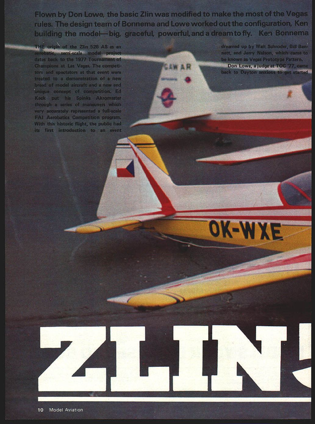
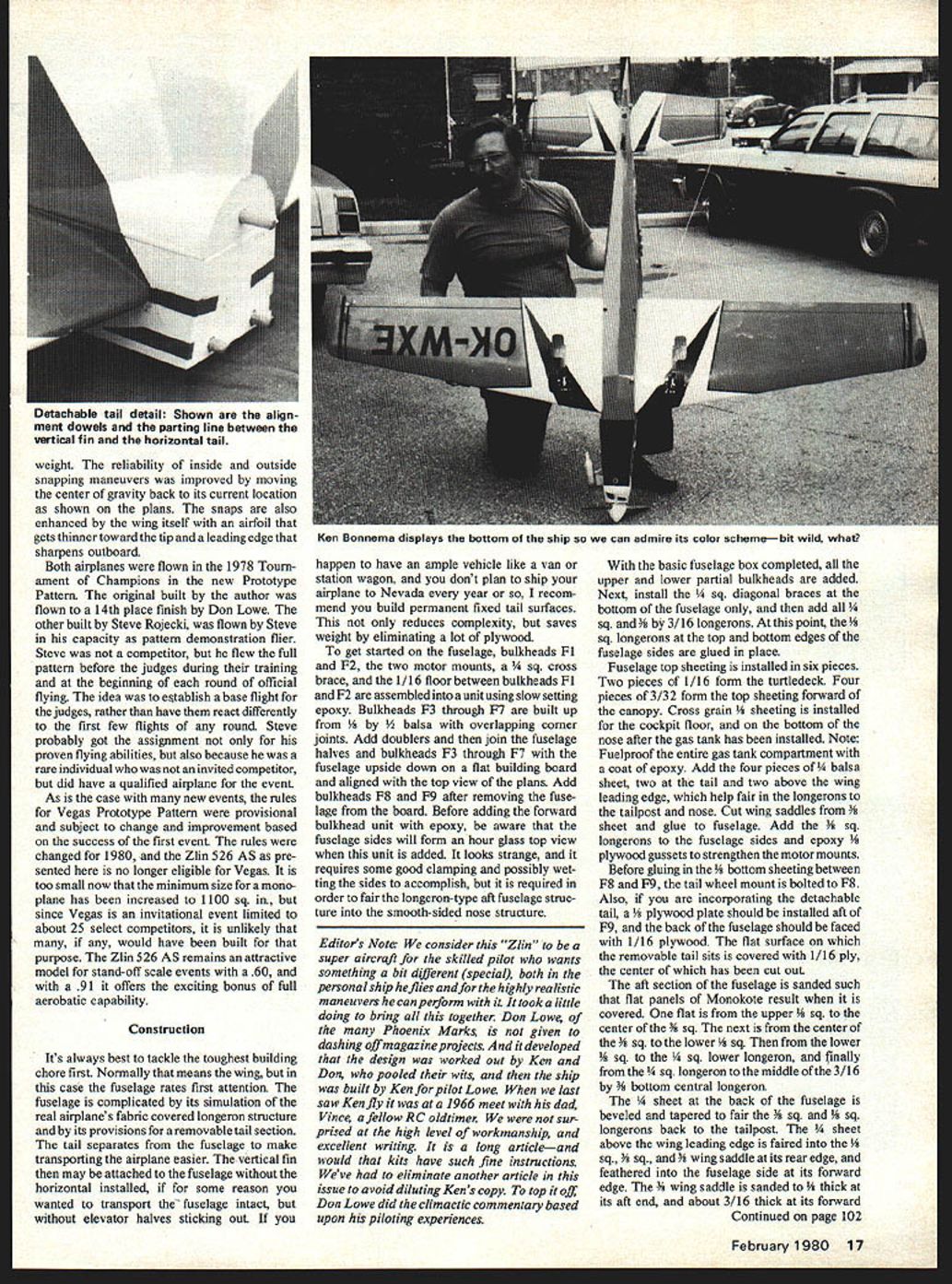
Flown by Don Lowe, the basic Zlin was modified to make the most of the Vegas rules. The design team of Bonnema and Lowe worked out the configuration, Ken building the model—big, graceful, powerful, and a dream to fly. — Ken Bonnema
The origin of the Zlin 526 AS as an aerobatic, semi-scale model project dates back to the 1977 Tournament of Champions at Las Vegas. Competitors and spectators were treated to a demonstration of a new breed of model aircraft and a new and unique concept of competition. Ed Keck put his Spinks Akromaster through a series of maneuvers that very accurately represented a full-scale FAI aerobatic competition program. With this historic flight, the public had its first introduction to an event dreamed up by Walt Schroder, Bill Bennett, and Jerry Nelson, which came to be known as Vegas Prototype Pattern.
Don Lowe, a judge at TOC '77, returned to Dayton eager to start on a Vegas-type airplane. His enthusiasm was contagious; local modelers began to speculate on what type of aircraft would emerge for the event and how well a pattern pilot—used to fly-by maneuvers in an 11-minute flight—would adjust to 20 non-stop, in-sequence maneuvers representing only six fly-bys and approximately four minutes.
I got caught up in the excitement almost immediately. I've always considered myself a designer and a builder first, and a flier second. My goal has always been originality, and I jumped at the chance to get involved in the airplane design aspect of a new and totally unique event when Don asked if I'd be interested in developing a semi-scale aerobatic ship for him to fly at TOC '78.
Don and I sat down with the proposed rules for Prototype Pattern and began to formulate a systematic approach to selecting an aircraft and sizing the model. The rules stated that eligible aircraft had to have been designed expressly for, or flown in, international aerobatic competition. Scale requirements called for realistic paint schemes and no more than 15% deviation from any linear dimension. Aircraft type had to be maintained (low wing, shoulder wing, etc.), but airfoils and fuselage cross-section shape could be altered at the modeler's discretion. Monoplanes had to have at least 800 sq. in. of wing area; biplanes 1,000 sq. in. No model could exceed 22 pounds. There was no limitation on engine size or type.
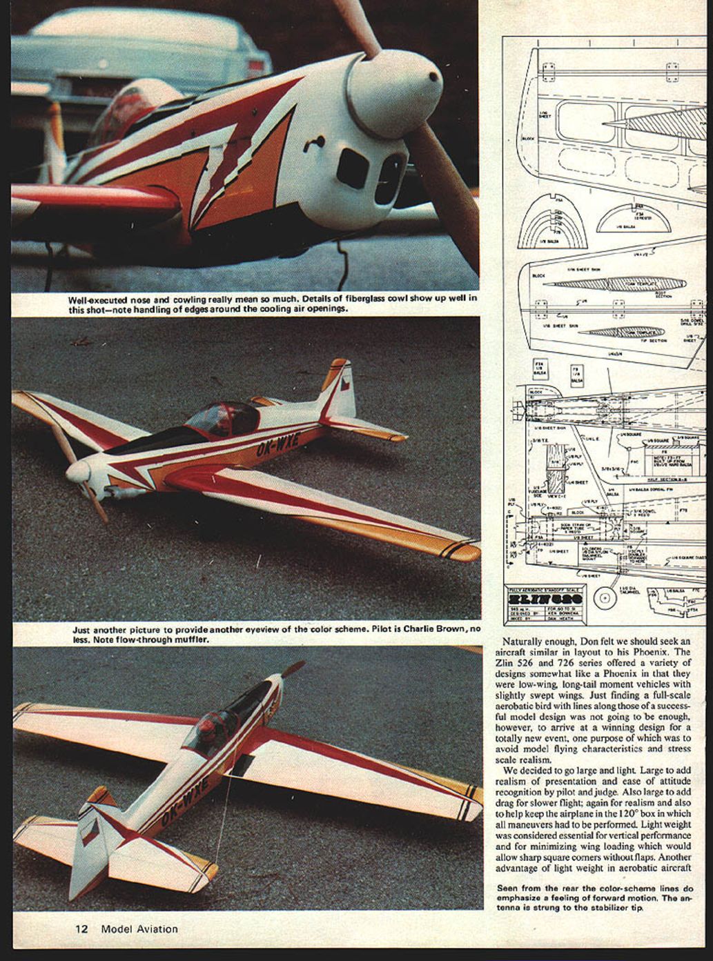
The guidelines left room for a virtually infinite variety of model size, weight, and type. Candidate aircraft ranged from Citabria to Hyper Bipe, with a full complement of Pitts, Zlins, Yaks, Chipmunks, and more in between. Don felt we should seek an aircraft similar in layout to his Phoenix. The Zlin 526 and 726 series offered a variety of designs somewhat like the Phoenix: low-wing, long-tail-moment vehicles with slightly swept wings.
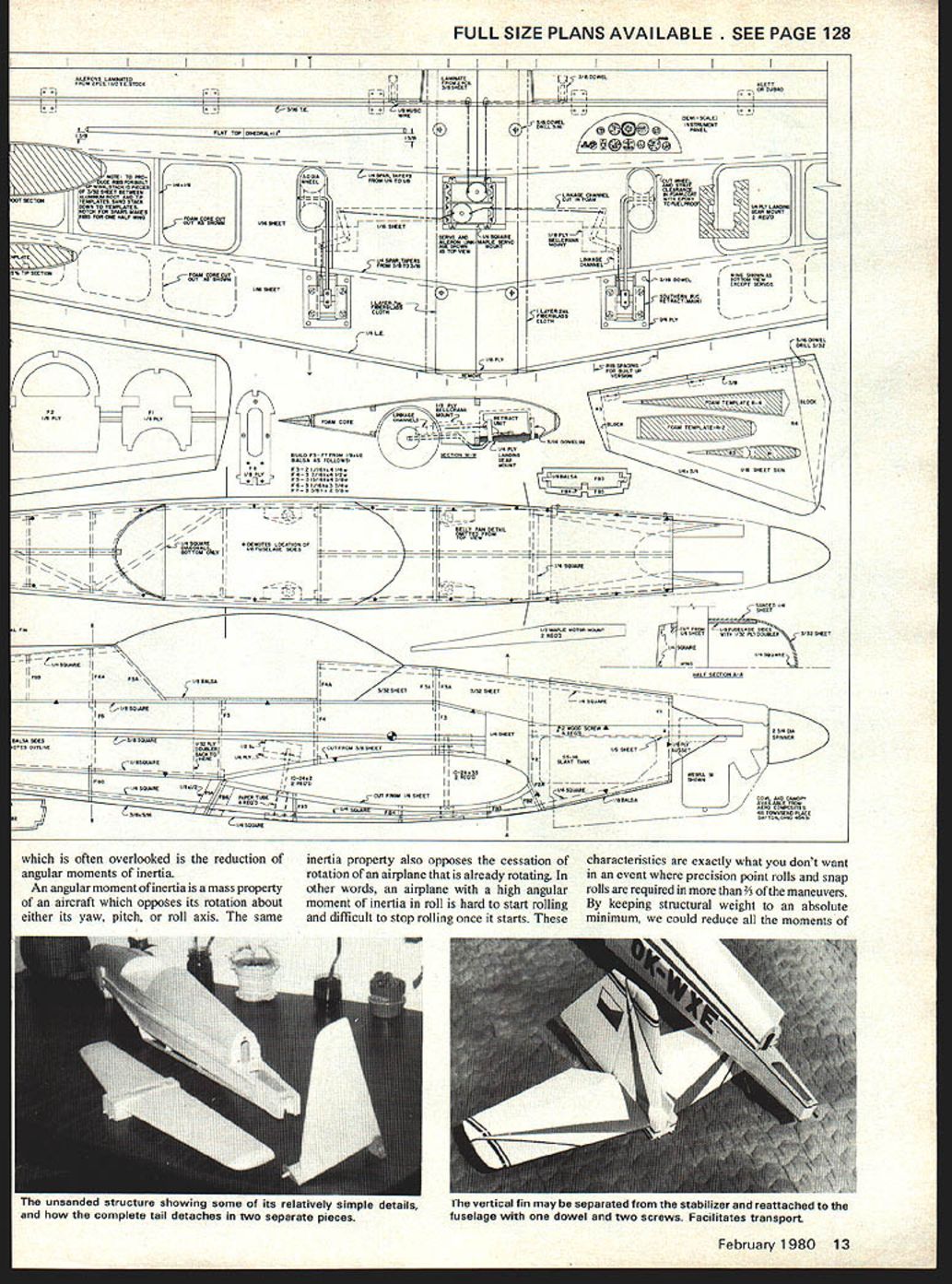
We decided to go large and light. Large for realism of presentation and ease of attitude recognition by pilot and judge, and to add drag for slower flight (to help keep the airplane in the 120° box in which maneuvers had to be performed). Light weight was essential for vertical performance and to minimize wing loading, allowing sharp square corners without flaps. Another advantage of light weight is reduction of angular moments of inertia. Angular moment of inertia is a mass property that opposes rotation about the yaw, pitch, or roll axis and also opposes cessation of rotation. For precision point rolls and snap rolls, high angular inertia is undesirable: it makes the airplane hard to start and stop rotating. Minimizing moments of inertia was a key design goal to ensure crisp, totally controllable rotations about all axes.
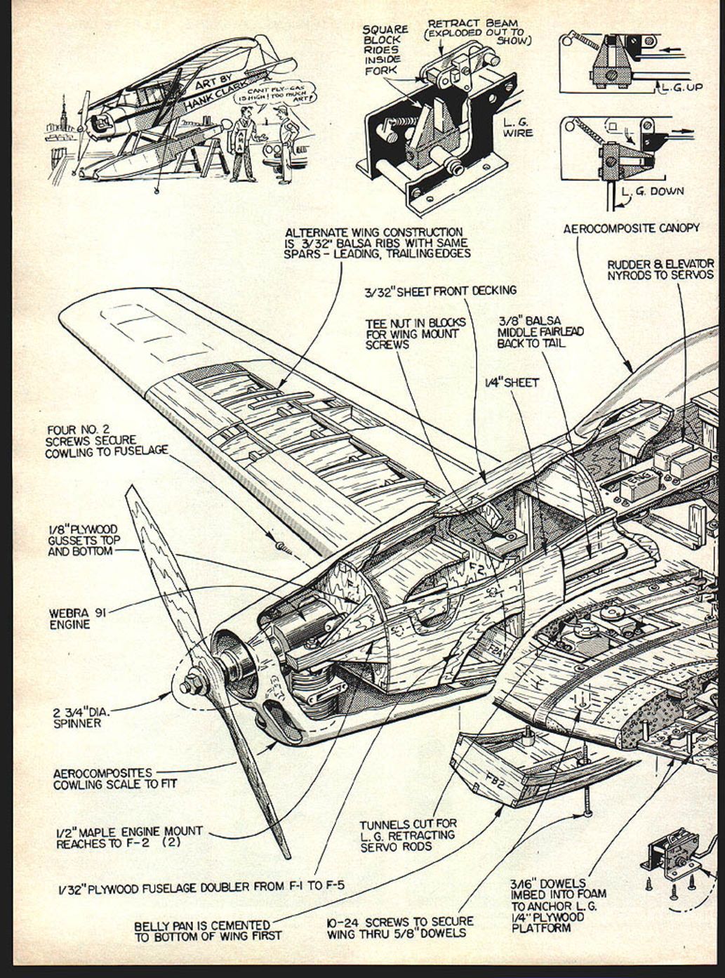
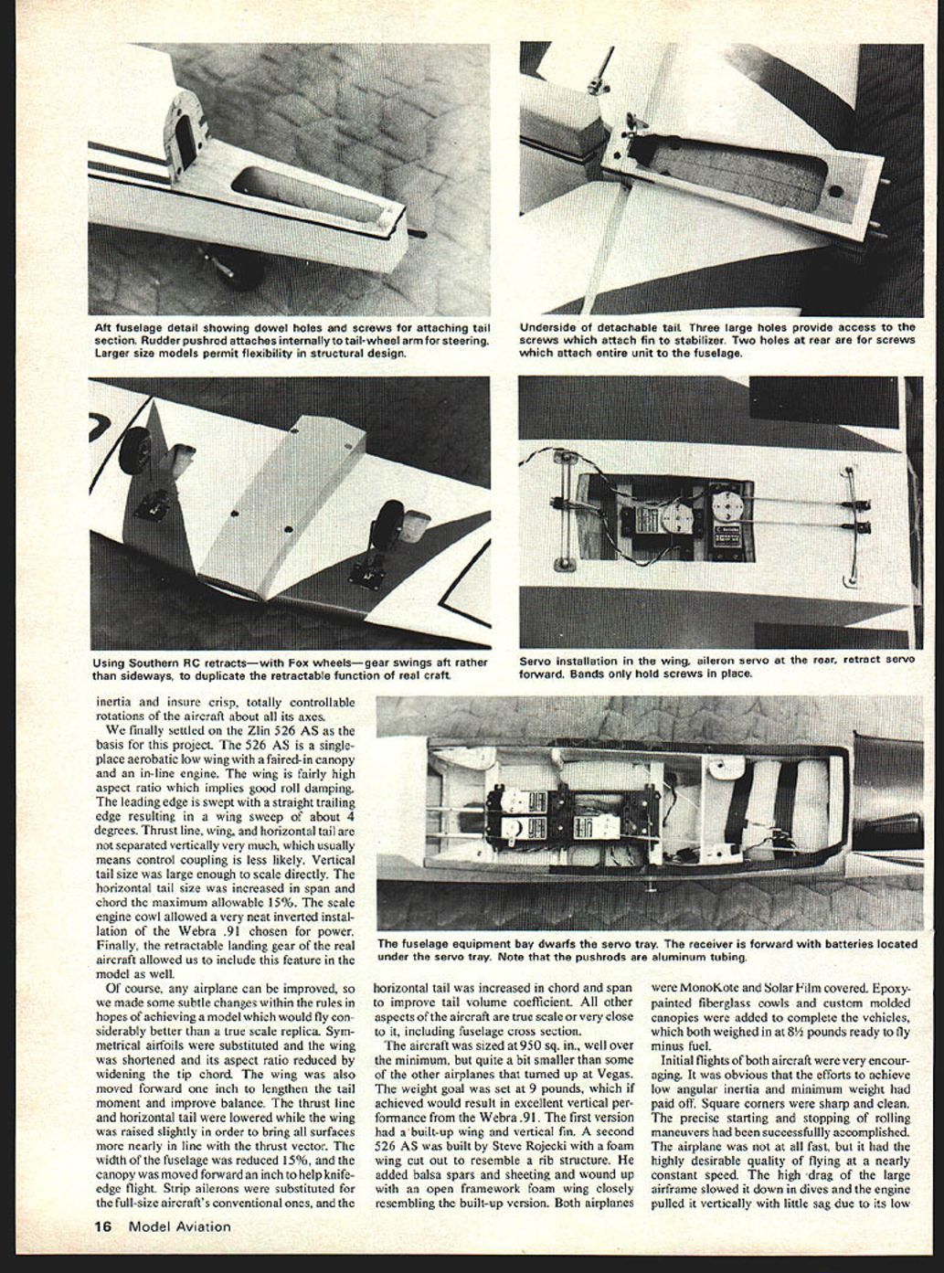
We finally settled on the Zlin 526 AS as the basis for the project. The 526 AS is a single-place aerobatic low wing with a faired-in canopy and an inline engine. The wing is fairly high aspect ratio, implying good roll damping. The leading edge is swept with a straight trailing edge resulting in about 4° sweep. Thrust line, wing, and horizontal tail are not separated vertically very much, which tends to reduce control coupling. Vertical tail size was large enough to scale directly; the horizontal tail was increased in span and chord the maximum allowable 15%. The scale engine cowl allowed a neat inverted installation of the Webra .91 chosen for power. The retractable landing gear on the full-scale aircraft allowed inclusion of retraction in the model.
Of course any airplane can be improved, so we made some subtle changes within the rules to achieve a model that would fly better than a true scale replica. Symmetrical ailerons were substituted and the wing was shortened and its aspect ratio reduced by widening the tip chord. The wing was moved forward 1" to lengthen the tail moment and improve balance. The thrust line and horizontal tail were lowered while the wing was raised slightly to bring all surfaces more nearly in line with the thrust vector. Fuselage width was reduced 15%, and the canopy was moved forward and inset to help knife-edge flight. Strip ailerons were substituted for the full-size conventional ones, and the horizontal tail was increased in chord and span to improve tail volume coefficient. All other aspects remained true scale or very close, including fuselage cross-section.
The aircraft was sized at 950 sq. in., well over the minimum but smaller than some other airplanes at Vegas. The weight goal was 9 lb; the first versions achieved about 8-3/4 lb ready to fly minus fuel. The first version had a built-up wing and vertical fin. A second 526 AS, built by Steve Rojecich, used a foam wing cut out to resemble a rib structure with balsa spars and sheeting, resulting in an open framework foam wing closely resembling the built-up version. Both airplanes were MonoKote and Solar Film covered, with epoxy-painted fiberglass cowls and custom molded canopies.
Initial flights of both aircraft were very encouraging. The efforts to achieve low angular inertia and minimum weight paid off: square corners were sharp and clean; starting and stopping rolling maneuvers were precise. The airplane was not fast, but it tended to fly at nearly constant speed. The large airframe's drag slowed it in dives while the Webra .91 pulled it vertically with little sag due to the low weight. Snapping maneuvers were improved by moving the center of gravity back to the location shown on the plans. The wing itself helped snaps: the airfoil thins toward the tip and the leading edge sharpens outboard.
Both airplanes were flown in the 1978 Tournament of Champions in the new Prototype Pattern. The original, built by the author, was flown to a 14th-place finish by Don Lowe. The other, built by Steve Rojecich, was flown by Steve as a pattern demonstration ship before the judges during their training and at the beginning of each round; the idea was to establish a base flight for the judges rather than have them react differently to the first few flights of any round.
As is often the case with new events, the rules for Vegas Prototype Pattern were provisional and subject to change. The rules were changed for 1980, and the Zlin 526 AS as presented here is no longer eligible for Vegas: the minimum monoplane size was increased to 1,100 sq. in. The Zlin 526 AS remains an attractive model for stand-off scale events with a .60 engine, and with a .91 it offers full aerobatic capability.
Construction
It's best to tackle the toughest building chore first. Normally that means the wing, but in this case the fuselage rates first attention. The fuselage is complicated by its simulation of the real airplane's fabric-covered longeron structure and by its provision for a removable tail section. The tail separates from the fuselage to make transporting the airplane easier. The vertical fin can be attached to the fuselage without the horizontal installed, if you want to transport the fuselage intact without elevator halves sticking out. If you have an ample vehicle (van or station wagon) and you don't plan to ship your airplane often, consider building permanent fixed tail surfaces to reduce complexity and save weight.
Fuselage
To get started on the fuselage, assemble bulkheads F1 and F2, the two motor mounts, a 1/4" sq. cross brace, and the 1/16" floor between F1 and F2 into a unit using slow-setting epoxy. Bulkheads F3 through F7 are built up from 3/8" by 1/4" balsa with overlapping corner joints. Add doublers and then join the fuselage halves and bulkheads F3 through F7 with the fuselage upside down on a flat building board, aligned with the top view of the plans. Add bulkheads F8 and F9 after removing the fuselage from the board.
Before adding the forward bulkhead unit with epoxy, note that the fuselage sides will form an hourglass top view when this unit is added. It looks strange and requires good clamping and possibly wetting the sides, but it is necessary to fair the longeron-type aft fuselage structure into the smooth-sided nose structure.
With the basic fuselage box completed, add all upper and lower partial bulkheads. Install the 1/4" sq. diagonal braces at the bottom of the fuselage only, then add all 1/4" and 3/16" longerons. Glue the 3/16" longerons at the top and bottom edges of the fuselage sides.
Fuselage top sheeting is installed in six pieces: two pieces of 1/16" form the turtledeck; four pieces of 3/32" form the top sheeting forward of the canopy. Cross-grain 1/8" sheeting is installed on the cockpit floor and on the bottom of the nose after the gas tank has been installed. Note: fuelproof the entire gas tank compartment with a coat of epoxy. Add four pieces of 1/4" balsa sheet—two at the tail and two above the wing leading edge—to fair the longerons to the tailpost and nose. Cut wing saddles from 3/8" sheet and glue to the fuselage. Add the 3/16" sq. longerons to the fuselage sides and epoxy 1/8" plywood gussets to strengthen the motor mounts.
Before gluing in the 1/8" bottom sheeting between F8 and F9, bolt the tailwheel mount to F8. If incorporating the detachable tail, install a 3/8" plywood plate at F9 and face the back of the fuselage with 1/16" plywood. The tail surface on which the removable tail is installed is covered with 1/16" ply, the center of which has been cut out.
The aft section of the fuselage is sanded so that flat panels result when it is covered. The flats are created between specified longerons and are faired with the 1/4" and 3/8" sheet pieces. Bevel and taper the 1/4" sheet at the back of the fuselage to fair the 1/8" and 1/4" sq. longerons back to the tailpost. Fair the 3/8" sheet above the wing leading edge into the 1/4", 3/8", and 3/16" longerons; sand a wedge into its rear edge and feather it into the fuselage side at its forward edge. Sand the wing saddle to taper from about 3/16" thick at the forward end to 1/8" thick at the aft end.
Spot epoxy the wing hold-downs, but do not drill them yet.
Editor's Note: We consider this Zlin to be a superb aircraft for a skilled pilot who wants something a bit different—both in appearance and in the highly realistic maneuvers it can perform. It took effort to bring it together: Don Lowe and Ken Bonnema pooled their ideas, and Ken built the ship for Don. The workmanship is of a high level, and the design and construction information here are detailed and useful.
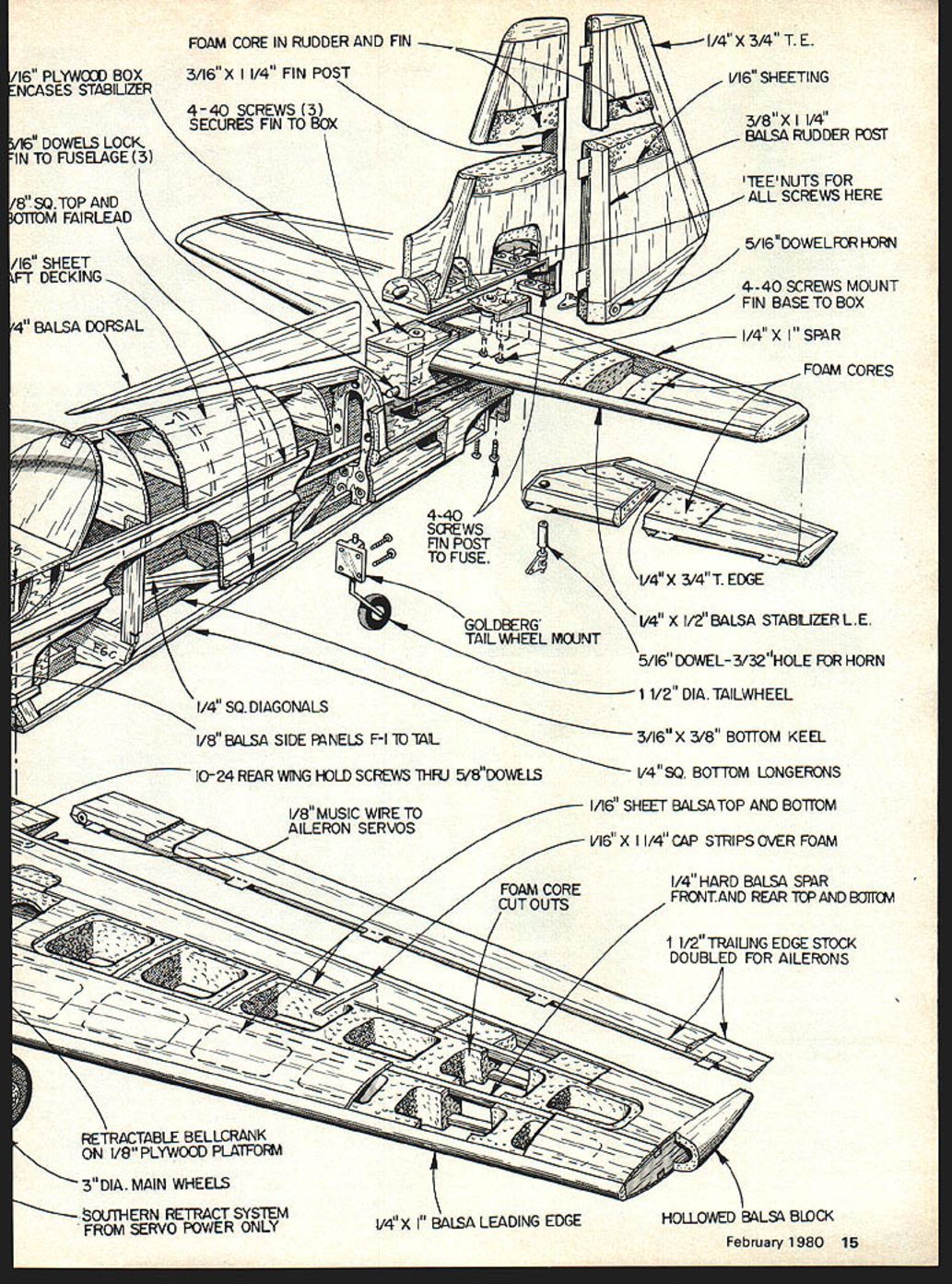
Parts / Components (from plans)
Full-size plans available — see page 128.
- 1/16" plywood box encases stabilizer
- 5/16" dowels lock fin to fuselage (3)
- 3/8" sq. top and bottom fairlead
- 1/16" sheet craft decking
- 1/4" balsa dorsal
- Foam core in rudder and fin
- 3/16" x 1 1/4" fin post
- 4-40 screws (3) secure fin to box
- 1/4" x 3/4" trailing edge (T.E.)
- 1/16" sheeting
- 3/8" x 1 1/4" balsa rudder post
- Tee nuts for all screws here
- 5/16" dowel for horn
- 4-40 screws mount fin base to box
- 1/4" x 1" spar
- Foam cores
- 1/4" x 3/4" T.E.
- 1/4" x 1/2" balsa stabilizer leading edge
- 5/16" dowel - 3/32" hole for horn
- 1 1/2" dia. tailwheel
- 3/16" x 3/8" bottom keel
- 1/4" sq. bottom longerons
- 1/16" sheet balsa top and bottom
- 1/16" x 1 1/4" cap strips over foam
- 1/4" hard balsa spar front and rear top and bottom
- Foam core cutouts
- 1 1/2" trailing edge stock doubled for ailerons
- Hollowed balsa block
- 1/4" x 1" balsa leading edge
- Goldberg tailwheel mount
- 4-40 screws fin post to fuselage
- 1/4" sq. diagonals
- 1/8" balsa side panels F-1 to tail
- 10-24 rear wing hold screws through 5/8" dowels
- 1/8" music wire to aileron servos
- Retractable bellcrank on 1/8" plywood platform
- 3" dia. main wheels
- Southern retract system from Servo Power only
The goal of these choices is minimum structural inertia and crisp, controllable rotations about all axes.
Wing
The plans show a foam wing mainly because it is simpler to build and, as demonstrated by Rojecich's foam wing versus the built-up version, no weight penalty occurred. Each wing half should be cut from one 1/2 cu. ft. density foam block at least 5" thick. Face the blocks with a foam wire cutter to ensure they are square. Align root and tip templates on the block so there is absolutely no twist, and include dihedral by raising the centerline of the tip rib 0.70" above the root centerline.
Locate the root rib in the exact same place on both blocks so the wing halves may be joined in the blocks later. Cut out the core, including spar notches, using a hot-wire bow. Number the rib templates beforehand in equal chord percentage segments so the hot wire may be drawn past identical chord stations on both root and tip templates.
After cutting the cores, cut templates for the cutouts in the cores. Place the cores back in their blocks, sandwich together, and place a template on each side. To cut the open areas, push a piece of 1/16" music wire through the space to be cut out. Slip a center-drilled piece of 1/4" dowel rod over each end of the wire and attach current-regulated hot leads outside the dowels. Holding the new hot wire by the wooden dowels, run it around the inside of the templates to cut out the area. Repeat for each cutout.
Tapered spars are cut from very hard 1/8" balsa and glued in the cores with Titebond or epoxy. Keep the cores in their blocks and weight them on a flat surface while the spars dry. Cut landing gear unit clearance, wheel wells, servo boxes, and linkage channels with copper wire forms placed in a heavy-duty soldering gun.
Epoxy in the 1/4" landing gear mounting plates with their 4-40 blind nuts already installed. These plates each have four 3/16" dowels protruding into the foam for extra gluing area and strength. Glue in 1/8" ply bellcrank mounts and install bellcranks and landing gear linkage. Sheet the center section, leading edge, and trailing edge with 1/16" balsa sheet. Use slow-setting epoxy sparingly on the balsa only—spreading epoxy on the foam does not improve bond and adds weight. Set the cores back in their blocks and weight on a flat surface while sheeting dries.
After sheeting dries, trim excess and sand flush with the foam. Add tip blocks, 3/16" trailing edge, 1/4" leading edge, and cap strips. Remove sheeting covering the wheel wells and landing gear cavity. Join the wing halves on a flat surface by epoxying the center section with both halves resting in their foam blocks. Weight and allow adequate time for epoxy to set.
Ailerons are laminated from two pieces of 1/8" trailing edge stock glued longest-surface to longest-surface. Sand additional leading-edge bevel as needed for aileron throw. Embed a 3/16" dowel drilled for 1/8" wire near the aileron root. 1/8" wire aileron horns are essential; an experiment with 3/32" wire resulted in aileron flutter.
The fixed portion of the wing trailing edge between the ailerons is laminated from 3/8" balsa sheet. Notch clearance for the 1/8" wire into its front. Install aileron horn wires with brass or nylon guides before gluing on this central trailing edge section.
Drill holes through the wing and epoxy in four 5/16" dowels drilled through for 3/16" wing bolts. Sand these flush with the wing surfaces. Reinforce the wing center section by wrapping first with a layer of 7-oz. fiberglass cloth and then with 2-oz. cloth. Drill through the hardened fiberglass to open the wing-bolt holes. Set and align the wing on the fuselage carefully.
Run a long 3/16" drill through the bolt holes already in the wing and drill through the plywood wing-mounting plates in the fuselage. Remove the wing, enlarge the holes in the fuselage plates, and install 10-24 blind nuts. Bolt the wing to the fuselage and build up the belly pan to align perfectly with the fuselage. Use paper tubes as bolt guides through the belly pan. Cut away fiberglass and balsa sheet covering the servo box and install rails for aileron and retract servos.
For a built-up wing: rib spacing is shown on the plans. Using tip and root templates, sandwich 15 pieces of 3/32" balsa between templates and sand the stack down to form ribs for one wing half. Spar location and size are unchanged from the foam wing. Leading edge, trailing edge, sheeting, and cap strips are also unchanged, but glue 1/16" vertical-grain balsa spar webbing between all ribs on both front and rear spars. Reinforce ribs on either side of the landing gear mount with plywood. Build wheel wells from 1/16" balsa sheet. Ailerons, tips, and center section including fiberglass reinforcement are unchanged.
Tail Surfaces
Cut foam cores for the vertical fin, rudder, stabilizer, and elevator using the templates. Epoxy 1/16" sheeting on as with the wing and leave surfaces to dry while weighted in their foam blocks. Glue on leading and trailing edges and tip blocks after sheeting is trimmed and sanded.
Note: the 3/16" vertical fin trailing edge is glued to the foam core before sheeting, with the sheeting overlapping it. Elevators and rudder use a 3/32" wire control horn drilled for 3/32" wire.
Wrap the joined stabilizer halves with fiberglass cloth as shown on the plans.
If you are incorporating the removable tail, adhere to these steps carefully:
- Spot-glue a mating piece of 1/16" plywood on top of the plywood tail-mounting surface on the fuselage. This upper piece should be about 1/4" shorter than the fuselage piece.
- At the front edge of this piece, glue on another piece of 1/16" plywood matching the upper middle quarter of F8, including two 3/16" dowel holes. Insert two 3/16" dowels through these holes and glue them only to the plywood floor. Do not glue the dowels to F8.
- At the back edge of the plywood floor glue on F9A (1/8" balsa). Glue on 1/8" balsa lower saddles for the stabilizer.
- Align stabilizer carefully and glue saddles. Glue on 1/8" balsa upper stabilizer saddles and cap the top of saddles with 1/16" plywood. You should now have a box structure surrounding the stabilizer with plywood bottom, top, and front, and a balsa back. Do not separate from the fuselage yet.
- Spot-glue another piece of 1/16" plywood to the top of the box structure. At the front edge of this piece, glue on a piece matching the uppermost portion of F8 including the 3/16" dowel hole. Glue two blocks of 1/8" plywood to the top of the plywood floor as shown on the plans. Drill one 4-40 clearance hole through the center front block and through the stabilizer box. Drill two 4-40 clearance holes through the rear block and through the stabilizer box. Enlarge all three holes in the 1/8" ply blocks only and install 4-40 blind nuts. Insert a piece of 3/16" dowel through its hole and glue it to the plywood floor only. Do not glue dowel to F8.
- Spot-glue a piece of 1/8" plywood to the original 1/16" plywood tail mounting surface in the half-inch space left behind the stabilizer box. This 1/8" block should fill the space but be 1/16" short in width on both sides. Drill two 4-40 clearance holes through this block and the corresponding block in the fuselage underneath. Enlarge holes in the upper block only and install two 4-40 blind nuts. Glue a piece of 1/16" plywood matching the back face of the stabilizer box to the 1/8" plywood piece just installed and to the 1/16" plywood floor spot-glued to the top of the stabilizer box. Do not glue this piece to the stabilizer box.
- Take the sheeted vertical fin with its extended hinge-line post and cut clearance in the bottom for the two plywood blind-nut blocks and the 3/16" dowel mounted on the upper plywood floor. Trim the rudder post so it just contacts the plywood blind-nut block behind the stabilizer box, and trim the vertical fin sheeting so it fits over the outside edges of the plywood block and lines up with the fuselage sides. Glue the vertical fin to the upper plywood floor and to the plywood pieces behind the stabilizer box. Be careful not to glue the vertical fin assembly to the stabilizer box. Glue in and sand two balsa blocks that fair the vertical fin into F8. Finally, add the 1/4" balsa dorsal fin to the assembly.
- When dry, separate the vertical fin assembly from the fuselage and the stabilizer box using a razor blade to break the spot-glue joints, then separate the stabilizer box from the fuselage in the same way. Enlarge the three holes in the stabilizer box from its lower side: the holes should be opened only in the lower plywood floor and in the stabilizer itself. Do not enlarge the holes in the upper plywood cap. Glue in paper straws to act as screw guides.
If you prefer a fixed tail, eliminate the removable-tail plywood pieces, enlarge the balsa pieces accordingly, and glue everything together permanently.
Finishing
MonoKote or Solar Film is strongly recommended. These materials closely simulate the fabric covering of the full-scale airplane and offer the lightest overall weight for a complete finish.
A fiberglass engine cowl and a molded cellulose-acetate canopy are available from Aerocomposites Corp., 411 Townsend Place, Dayton, Ohio 45431. The cowl and the framework molded in the canopy are painted to match the Monokote colors used. The paint scheme on OK-WKE represents Czechoslovakian Team colors; another shown is in British Aerobatic Team colors. Many countries fly the Zlin, so there are many color-scheme options.
Installation
Radio installation is straightforward. With a .60 engine, stow the flight-pack battery above the gas tank. With a .91, locate the battery above the servo tray or further aft as necessary to achieve the proper CG. The receiver is foam-wrapped and sits in the fuselage bay just in front of the servo tray.
Aileron and retract linkage are as shown on the drawings. The plans show independent control horns on each elevator half, which require a "Y" pushrod that exits the rear fuselage on both sides. As an alternative, the elevator halves may be joined to a central horn with a single pushrod concealed in the fuselage. The rudder pushrod may be attached internally to the tailwheel steering arm before it exits the fuselage side on its way back to the rudder.
Flying the 526 AS
The Zlin is designed as a high-performance machine capable of performing all AMA, FAI, and Aerobatic Tournament maneuvers. Flying the aircraft is a pleasure and not difficult considering its high performance potential. Takeoffs are easy. Landings require a little care to prevent tip stall but remain slow due to the generous wing area. I do not recommend dragging it in with the nose high; very docile landings can be achieved (with some sacrifice of snapping capability) by blunting the wing leading edge toward the tip.
You can adjust performance by starting with a forward CG and slowly moving it back to improve snapping and roll characteristics. I used a fairly aft CG to get the best performance in snaps and rolls. I also experimented with wing incidence and engine thrust line. A zero-zero setup (zero incidence, zero thrust) works well with a little right engine thrust to ease torque effects.
The Webra .91 pulls the aircraft along with ease using a 14x6 or 14x7 prop. I used a non-stock .60-size Perry pump carburetor on the Webra; since it will only turn 10,500–11,000 rpm with that carb, prop choice becomes critical. Vertical performance suffers first if engine and prop are mismatched in large, high-drag airplanes like this one.
Use very stiff torque and pushrods throughout, since control loads are high. Heavy servos without extremely tight centering or resolution are recommended. Rapid potentiometer wear can occur if servos are too tight due to control loads and increased control surface "dither." Fortunately, these large slow aircraft are more tolerant of control dead-band than high-speed pattern ships.
You will especially appreciate the very tight looping and cornering capability of the Zlin. The large wing with low wing loading gives spectacularly tight square loops. Rolling maneuvers require a little more work than a standard pattern ship due to reduced airspeed, smaller power loading, and the somewhat short-coupled design—these large, slower aircraft require increased proficiency with the rudder. The Zlin combines realistic looks with fine aerobatic performance. What more could a modeler ask?
Transcribed from original scans by AI. Minor OCR errors may remain.

